GENERAL DESCRIPTION
Note the symmetrical structure between channel 1 and 2 on one hand and channel 3 and 4
on the other hand.
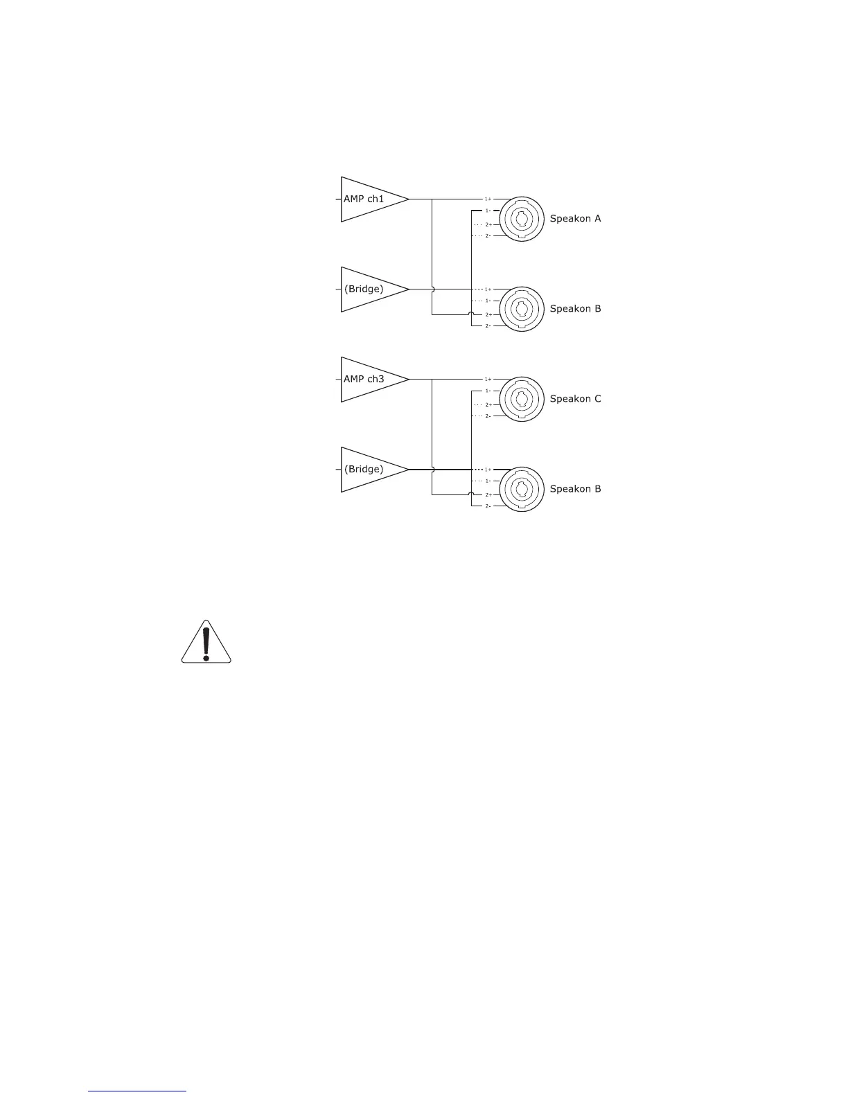
When using the NXAMP4x1 Powered TDcontroller in bridge mode, here is the output routing:
Now amplifier channel 1 and 2 works together in bridge mode (channel 2 is marked
“Bridge” above). This is same for channel 3 and 4. The pin-out on the speakon is the same
as the channel 1 and 3 in non bridge mode, thanks to the programmable routing unit (not
drawn here).
You can see with the dashed line on the above drawing that unused pins on
output speakon are shorted together, but are not connected to ground. Therefore be
careful as very high voltage might be present on these unused pins.
User interface block
The user interface block has already been described through the front panel description in
the first part of this document. Please note that all the commands and displays are
available through the ESmonitor software by Auvitran, through the Ethersound™ network
(except the mains switch).
Communication block
The communication block regroups the RS232 port (on a sub-D9 plug) and the GPIO port
(on a sub-D25 plug).
The RS232 port is mainly used to upgrade the firmware of the unit from a PC computer.
But it could also be used in the future for local communication with other equipments. The
PAGE 27 OF 80

 Loading...


