MENU DESCRIPTION
depressing the “A” button.
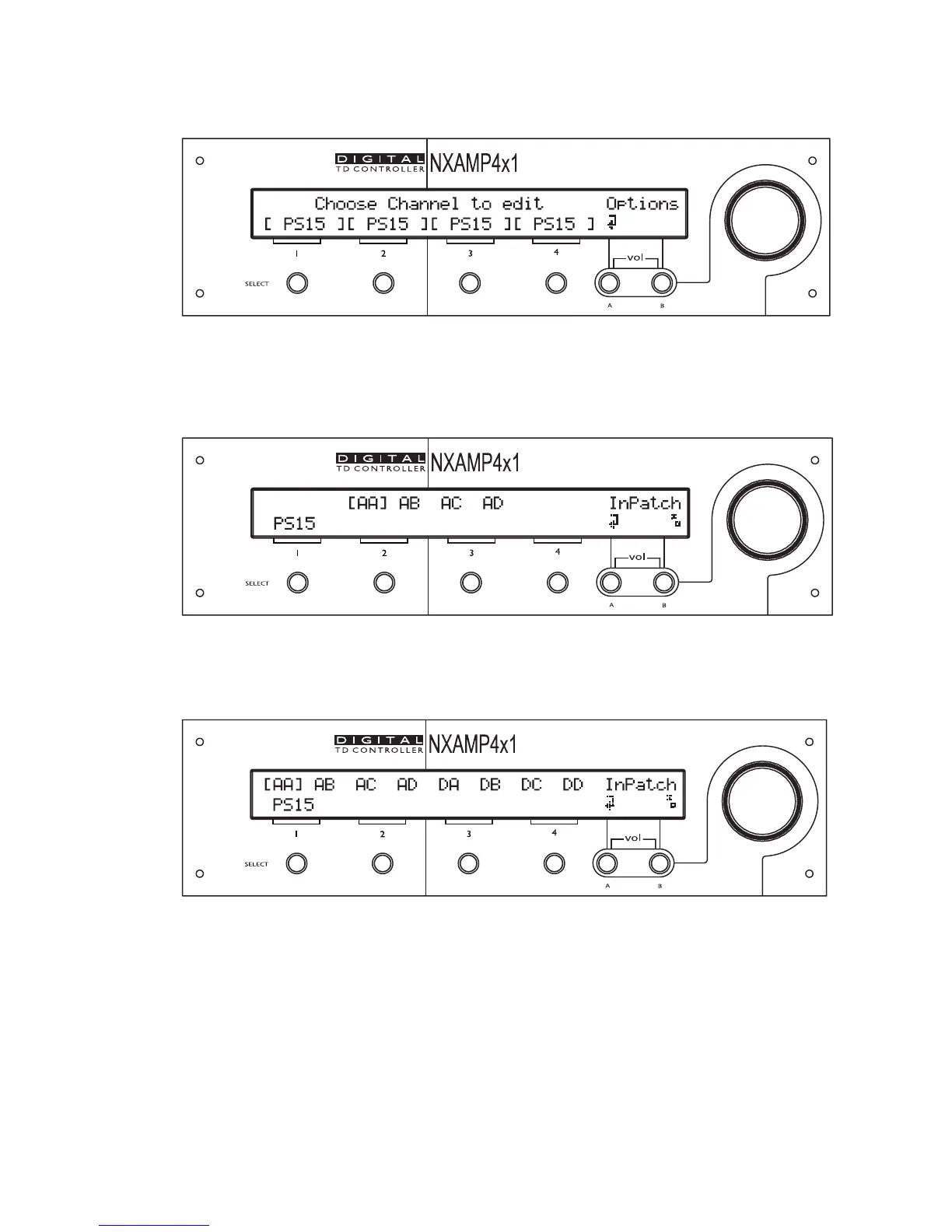
Now that one of the channels is selected, you can see the inputs available on the top line of
the screen. On the back of the amplifier, you can see Analog Input A, Analog Input B, and
so on. These inputs are named “AA” (for Analog input A), “AB” (for Analog input B), “AC”
(for Analog input C) and “AD” (for Analog input D).
If an optional board is fitted inside the expansion slot, then four Digital inputs will be
available too. These digital inputs are named “DA” (for Digital Input A), “DB” (for Digital
Input B), “DC” (for Digital Input C) and “DD” (for Digital Input D).
If one of the inputs is between brackets, it signifies that the input is currently patched to
the channel displayed on the bottom line of the screen (in the example above, Analog input
A (shown as AA) is patched to the PS15 on the channel 1 of the amplifier).
You can toggle the status of the input which is blinking by depressing the “B” button. If the
brackets appear around this input, the patch is ON, if it is clear, then the patch is OFF. You
can go from one input to the other by turning the wheel.
PAGE 42 OF 80

 Loading...


