20 – ENGLISH
“Table 12” and “Table 13” show the “Receiver outputs” and the
“Control unit inputs” associated with each.
Table 12
SMXI / SMXIS OR OXI / OXIFM / OXIT / OXITFM IN MODE 1 OR MODE
2
Receiver output Control unit input
Output No. 1
“SbS” (Step-by-Step) command
Output No. 2
“Partial opening 1” command
Output No. 3
“Open” command
Output No. 4
“Close” command
Table 13
OXI / OXIFM /OXIT / OXITFM IN MODE 2 EXTENDED
No. Command Description
1 Step-by-Step
“SbS” (Step-by-Step) command
2 Partial opening 1
“Partial opening 1” command
3 Open
“Open” command
4 Close
“Close” command
5 Stop
Stops the manoeuvre
6
Condominium
Step-by-Step
Command in condominium mode
7
High priority Step-
by-Step
Commands also with the automation
locked or the commands enabled
8 Partial open 2
Partial opening (the M2 gate leaf
opens to 1/2 the full length)
9 Partial open 3
Partial open (the two gate leaves
open to 1/2 the full length)
10
Opens and locks
the automation
Triggers an opening manoeuvre
and, once this terminates, locks the
automation; the control unit will not
accept any command other than
“High priority Step-by-Step” and
automation “Unlock”, or (only from
Oview) the following commands:
“Unlock and close” and “Unlock and
open”
11
Closes and locks
the automation
Triggers a closing manoeuvre and,
once this terminates, locks the
automation; the control unit will not
accept any command other than
“High priority Step-by-Step” and
automation “Unlock”, or (only from
Oview) the following commands:
“Unlock and close” and “Unlock and
open”
12 Lock automation
Triggers the stoppage of the
manoeuvre and locks the
automation; the control unit will not
accept any command other than
“High priority Step-by-Step” and
automation “Unlock”, or (only from
Oview) the following commands:
“Unlock and close” and “Unlock and
open”
13
Release
automation
Triggers unlocking of the automation
and restores normal operation
14
On Timer
Courtesy light
The courtesy light output switches on
with timer-based switching off
15
On-Off
Courtesy light
The courtesy light output switches on
and off in Step-by-step mode
l
For further information, consult the specic manual
of the receiver.
8.2 CONNECTING THE IBT4N INTERFACE
The control unit is equipped with a “IBT4N”-type connector for
the IBT4N interface, which allows for connecting all devices
equipped with BusT4 interface, such as, for example, Oview
programmers and the IT4WIFI Wi-Fi interface.
The Oview programmer allows for comprehensively and rapidly
managing the installation, maintenance and diagnosis of the en-
tire automated system.
f
Before connecting the interface, disconnect the
power supply to the control unit.
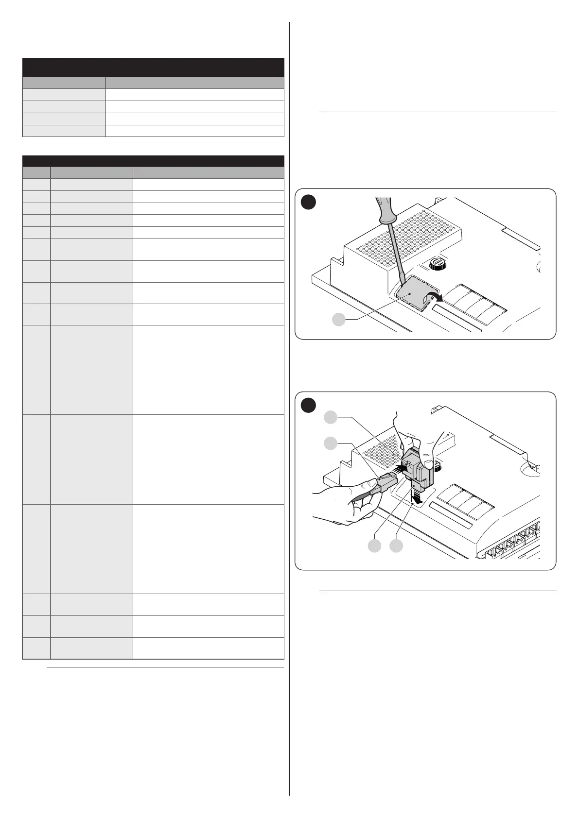
To install the interface (“Figure 24” and “Figure 25”):
1. remove the cover of the control unit’s containment box
2. remove the plastic pre-cut element (A) and check that
there are no burrs
A
24
3. place the interface (B) in the appropriate slot (C) on the
control unit’s electronic board
4. insert the cable (D) in the appropriate slot (E) on the in-
terface.
D
E
CB
25
At this stage, the control unit can be powered again.
l
For further information, consult the specic manu-
als of the connected devices.

 Loading...


