4 – ENGLISH
INSTALLATION
3
3 INSTALLATION
3.1 PRE-INSTALLATION CHECKS
Before proceeding with the product’s installation, it is necessary
to:
– check the integrity of the supply
– check that all the materials are in good working order and
suited to the intended use
– check that all operating conditions comply with that specied
in the “Product usage limits” paragraph and in the “TECHNI-
CAL SPECIFICATIONS” chapter
– check that the chosen installation location is compatible with
the product’s overall dimensions (see “Figure 2”)
– check that the surface chosen for installing the product is sol-
id and can ensure stable attachment
– make sure that the installation area is not subject to ooding; if
necessary, the product must be installed appropriately raised
above ground level
– check that the space around the product allows safe and easy
access
– check that all electrical cables to be used belong to the type
listed in “Table 1”
– check that the automation has mechanical stops in both the
opening and closing phases.
3.2 PRODUCT USAGE LIMITS
The product must be used exclusively with the gearmotors listed
in “Table 4” and in accordance with the corresponding usage
limits.
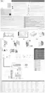
3.3 PRODUCT IDENTIFICATION AND OVERALL
DIMENSIONS
The overall dimensions and label (A) that allow for identifying the
product are shown in “Figure 2”.
232 mm
A
2
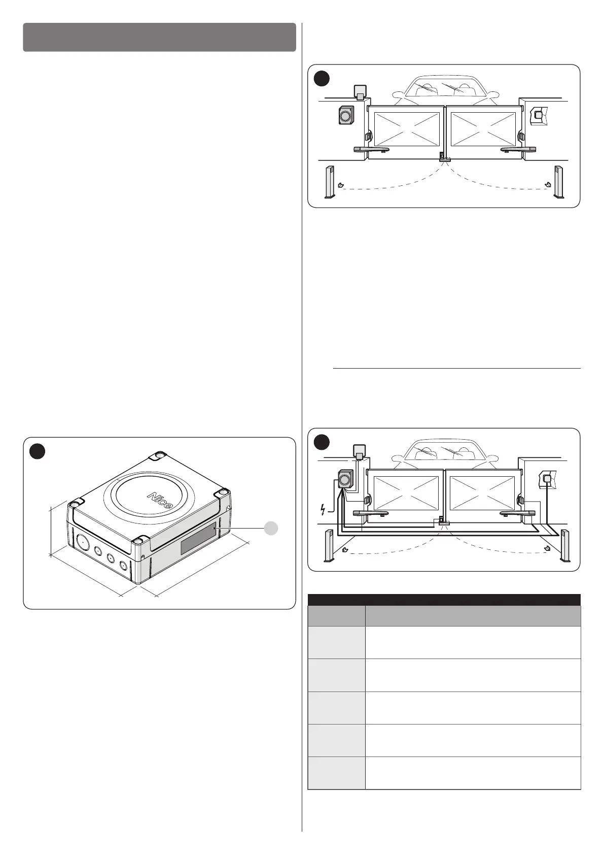
3.4 TYPICAL INSTALLATION
“Figure 3” shows an example of an automation system con-
structed using Nice components.
D
D
G
G
B
H
B
E
A
C
I
3
A Control unit
B Gearmotor
C Warning light
D Photocell
E Digital keypad - Transponder reader - Key selector
F Photocell column
G Mechanical stops for the open position
H Mechanical stop at closed position
I Electric lock
These above-mentioned components are positioned according
to a typical standard layout. Using the layout in “Figure 4” as a
reference, dene the approximate position in which each com-
ponent of the system will be installed.
a
Before proceeding with the installation, prepare the
required electrical cables by referring to “Figure 4”
and to that stated in the “TECHNICAL SPECIFICA-
TIONS” chapter.
b c
a
d
g
f-h
d d
e
d
4
Table 1
TECHNICAL SPECIFICATIONS OF ELECTRICAL CABLES
Identication
no.
Cable characteristics
a
CONTROL UNIT POWER SUPPLY cable
1 cable 3 x 1.5 mm
2
Maximum length 30 m [note 1]
b
WARNING LIGHT cable
1 cable 2 x 0.5 mm
2
Maximum length 20 m
c
ANTENNA cable
1 x RG58-type shielded cable
Maximum length 20 m; recommended < 5 m
d
BLUEBUS DEVICES cable
1 cable 2 x 0.5 mm
2
Maximum length 20 m [note 2]
e
KEY SELECTOR cable
2 cables 2 x 0.5 mm
2
Maximum length 50 m [note 3]

 Loading...