8 – ENGLISH
4.3 CONNECTING OTHER DEVICES TO THE
CONTROL UNIT
In any additional devices belonging to the system (e.g. tran-
sponder card reader, light for the key selector, etc.) must be
powered, they can be connected to the control unit using termi-
nals “SbS (positive)” and “Stop (negative)” (“Figure 7”). The
power supply voltage is 24 Vc with a maximum available cur-
rent of 200 mA.
l
The voltage available at the “SbS” and “STOP” ter-
minals remains even when the “Stand-by” function
is enabled on the board.
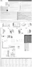
4.4 ADDRESSING OF DEVICES CONNECTED
WITH THE BLUEBUS SYSTEM
To allow the control unit to recognise the devices connected
through the “BlueBUS” system, these devices must be addressed.
This operation can be carried out by correctly positioning the
electrical jumper present in each device (also refer to the in-
struction manual of each device). Shown below is an address-
ing diagram for photocells, based on their type.
FOTO 1
FOTO
FOTO II
FOTO 1 II
FOTO 2 II FOTO 2
9
Table 3
PHOTOCELL ADDRESSES
Photocell
Position of the
jumpers
FOTO (PHOTO)
External photocell h = 50 activated during the
closing phase (stops and reverses the gate’s
movement)
FOTO II (PHOTO II)
External photocell h = 100 activated during the
closing phase (stops and reverses the gate’s
movement)
FOTO 1 (PHOTO 1)
Internal photocell h = 50 cm with activation
both during closing (stops and reverses the
movement) and during opening (stops and
restarts when the photocell disengages)
FOTO 1 II (PHOTO 1 II)
Internal photocell h = 100 cm with activation
both during closing (stops and reverses the
movement) and during opening (stops and
restarts when the photocell disengages)
FOTO 2 (PHOTO 2)
Internal photocell triggered during the
opening phase (stops and reverses the gate’s
movement)
FOTO 2 II (PHOTO 2 II)
Internal photocell triggered during the
opening phase (stops and reverses the gate’s
movement)
FOTO 3 (PHOTO 3)
CONFIGURATION NOT ALLOWED
m
At the end of the installation procedure, or after
photocells or other devices have been removed, it is
necessary to complete the learning procedure (see
the “Learning of connected devices” paragraph).
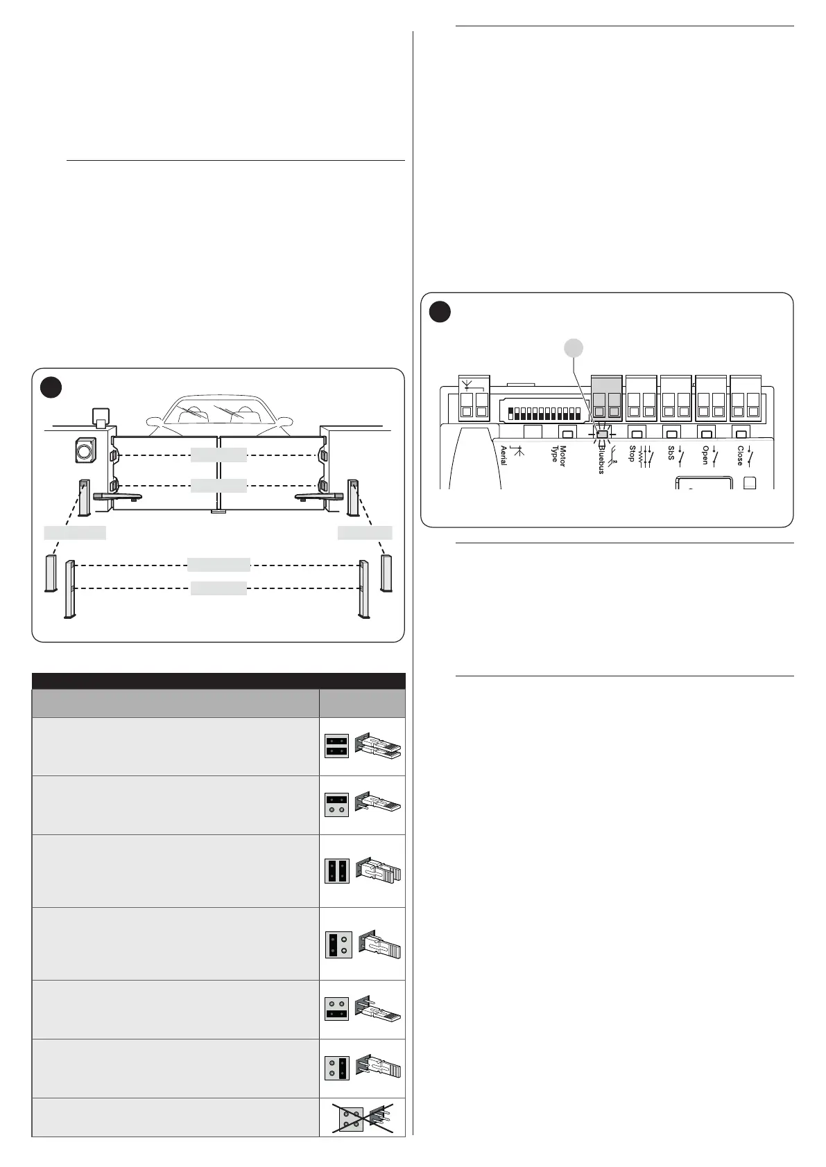
4.5 INITIAL START-UP AND ELECTRICAL
CONNECTIONS TEST
After powering the control unit, carry out the following checks
(“Figure 10”):
1. after a few seconds, check that the “Bluebus” (A) LED
ashes regularly with one ash per second
2. check that the LEDs of the photocells, both TX (transmis-
sion) and RX (reception), ash. The type of ash emitted
in this phase is not signicant
3. check that the warning light connected to the “Flash” out-
put is turned off.
CloseOpenSbSStop
Bluebus
1 2 3 4 5 6 7 8 9
10 11 12
A
10
a
If any one of these tests fails, disconnect the pow-
er supply to the control unit and check the various
electrical connections made previously.
4.6 LEARNING OF CONNECTED DEVICES
After the initial start-up, the control unit must recognise the de-
vices connected to the “Bluebus” and “Stop” inputs.
l
The learning phase must be carried out even if no
device is connected to the control unit.
The control unit can individually recognise the various devices
connected, thanks to the learning procedure, and detect possi-
ble anomalies.
For this to occur, the device learning procedure must be carried
out whenever a device is added or removed.

 Loading...