22 – ENGLISH
TECHNICAL SPECIFICATIONS
11
11 TECHNICAL SPECIFICATIONS
l
All technical specications stated in this section refer to an ambient temperature of 20°C (± 5°C). Nice S.p.A.
reserves the right to apply modications to the product at any time when deemed necessary, without altering
its functions and intended use.
Table 14
TECHNICAL SPECIFICATIONS
Description Technical specication
Mains power supply
MC824H control unit: 230 Va ±10% 50–60 Hz
MC824H/V1 control unit: 120 Va ±10% 50–60 Hz
Nominal power absorbed by the
mains grid
200 W
Power draw of the control unit battery
connector in “Stand-by all” mode
(including a receiver with SM-type
connector)
below 100 mW
Warning light output [Note 1]
1 ELDC warning light
Electric lock output [Note 1] 1 x 12 Va max 15 VA electric lock
Gate open indicator output [Note 1]
For 1 x 24 V maximum 4 W lamp (the output voltage may vary between –30% and +50% and
can also control small relays)
BLUEBUS output
1 output with maximum load of 15 Bluebus units (maximum 6 pairs of MOFB or MOFOB
photocells + 2 pairs of MOFB or MOFOB photocells addressed as opening devices +
maximum 4 MOMB or MOTB control devices
STOP input
for normally closed or normally open contacts or for 8.2 kΩ xed resistor contacts with self-
learning (any variation from the memorised status triggers the “STOP” command)
SbS input
for normally open contacts (the closing of the contact triggers the “Step-by-Step” command)
OPEN input
for normally open contacts (the closing of the contact triggers the “OPEN” command)
CLOSE input
for normally open contacts (the closing of the contact causes the “CLOSE” command)
Radio connector
SM connector for SMXI, OXI and OXFIM receivers
Radio ANTENNA input
50 Ω for RG58-type cable or similar
Programmable functions
8 ON-OFF and 8 adjustable functions
Self-learning functions
Self-learning of the devices connected to the BlueBus output; self-learning of the type of
device connected to the “STOP” terminal (NO, NC contact or 8.2 kΩ xed resistor); self-
learning of the gate leaf path and automatic calculation of the slowdown and partial opening
points (which vary depending on the type of installation)
Operating temperature
-20°C ... +55°C
Use in highly acid, saline or
potentially explosive atmosphere
NO
Protection rating
IP 54 with container intact
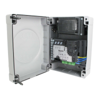
Dimensions (mm)
310 x 232 x H 122
Weight (kg)
4,1
Note 1 The “Warning light”, “Electric lock” and “Gate open indicator” outputs can be programmed with other functions (see “Table
6” in the “Level 1 programming (ON-OFF)” paragraph) or through the Oview programmer (refer to the “Connecting the
IBT4N interface” paragraph). The electrical characteristics of the output adapt to the programmed functions: warning light
(12 Vc, max 21 W lamp) - electric lock (12 Va, max 15 VA) - other outputs (all types: 1 x 24 V lamp or relayc, –30% to
+50%, 4 Wmax).

 Loading...