EasyManua.ls Logo

Nice MC824H User Manual

Nice MC824H
28 pages
To Next Page IconTo Next Page
To Previous Page IconTo Previous Page
Page #13 background imageLoading...
Page #13 background image
ENGLISH – 13
PROGRAMMING
6
6 PROGRAMMING
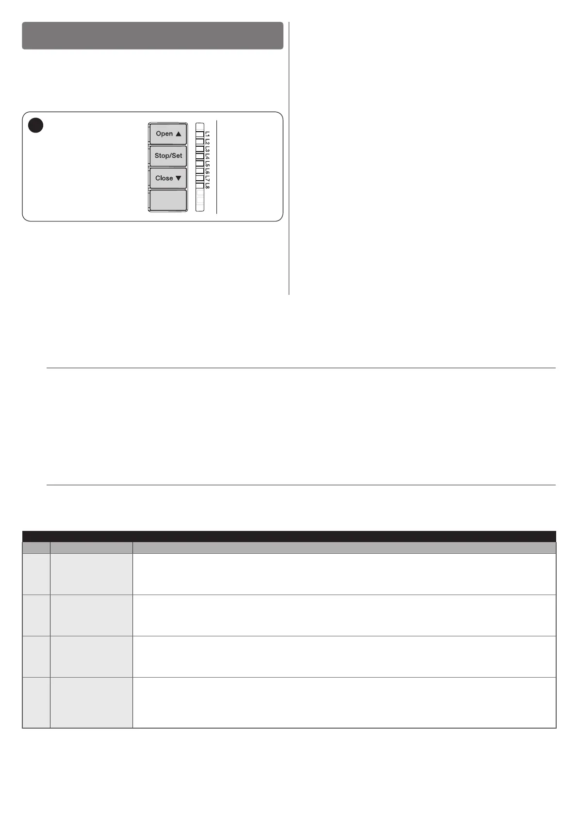
There are 3 buttons on the control unit:
f
,
g
and
h
(“Figure 18”) which can be used both to command
the control unit during the testing phase and to programme the
available functions.
The
i
button is not used.
18
The available programmable functions are grouped into two
levels and their operating status is signalled by eight LEDs “L1
... L8located on the control unit (LED lit = function enabled;
LED off = function disabled).
6.1 USING THE PROGRAMMING BUTTONS
f
Button for commanding the gate opening
Selection button during the programming phase.
g
Button used to stop a manoeuvre
If pressed for more than 5 seconds, it allows for entering
the programming mode.
h
Button for commanding the gate’s closure
Selection button during the programming phase.
i
Button not used.
6.2 LEVEL 1 PROGRAMMING (ON-OFF)
All the Level 1 functions are factory-set to “OFFand can be modied at any time. To check the various functions, refer to “Table 6”.
6.2.1 Level 1 programming procedure
m
The user has maximum 10 seconds to press the buttons consecutively during the programming procedure,
after which time the procedure terminates automatically and memorises the changes made up to then.
To perform Level 1 programming:
1. press and hold the
g
button until LED “L1” starts ashing
2. release the
g
button when LED “L1” starts ashing
3. press the
f
or
h
button to move the ashing LED to the LED associated with the function to be modied
4. press the
g
button to change the status of the function:
short ash = OFF
long ash = ON
5. wait 10 seconds (maximum time) to exit the programming mode.
l
To set other functions to “ON” or “OFF”, while the procedure is running, repeat points 2 and 3 during the phase
itself.
Table 6
LEVEL 1 FUNCTIONS (ON-OFF)
LED Function Description
L1 Automatic closing
Function ENABLED: after an opening manoeuvre there is a pause (equal to the set pause time), after
which the control unit automatically starts a closing manoeuvre. The pause time is set by default to 30
seconds.
Function NOT ENABLED: the system works in “semi-automatic” mode.
L2 Close after photo
Function ENABLED: if the photocells intervene during the opening or closing manoeuvre, the pause time
drops to 5 seconds regardless of the set “pause time”. With “automatic closing” disabled, if the photocells
intervene during the opening or closing manoeuvre, the “automatic closing” activates with the set “pause
time”.
L3 Always Close
Function ENABLED: in the event of a blackout, even of short duration, 10 seconds after the electricity
is restored the control unit detects that the gate is open and automatically starts a closing manoeuvre,
preceded by 5 seconds of pre-ashing.
Function DISABLED: when the electricity is restored, the gate remains in the same position.
L4 Stand-by all
Function ENABLED: 1 minute after the manoeuvre is completed, the control unit will turn off the “Bluebus”
output (connected devices) and all the LEDs, with the exception of the Bluebus LED, which will ash at a
slower speed. When the control unit receives a command, it restores normal operation (with a short delay).
This function is used to reduce consumption – an important aspect when the unit is powered by batteries
or photovoltaic panels.

Table of Contents

Other manuals for Nice MC824H

Questions and Answers:

Nice MC824H Specifications

General IconGeneral
BrandNice
ModelMC824H
CategoryControl Unit
LanguageEnglish

Summary

Nice MC824H Control Unit Overview

Installation and Usage Warnings

Instructions and warnings for installation and use of the control unit.

General Safety Warnings and Precautions

Important Safety Instructions

Crucial instructions for safe installation and personal safety.

European Legislation and Power Safety

Compliance with EU directives and power supply precautions.

User and Product Limitations

Information on user limitations, children's safety, and handling precautions.

Product Description and Intended Use

Control Unit Components Overview

Identification of the electronic command and control board components.

Installation Guide

Pre-Installation Checks and Usage Limits

Essential checks before installation and specified product usage limits.

Product Identification and Typical Layout

Product dimensions, label, and example of automation system layout.

Control Unit Mounting and Cable Entry

Steps for securely mounting the control unit and connecting cables.

Electrical Connections

Preliminary Checks and Wiring Diagram

Safety checks before connections and visual guide to wiring.

Terminal Descriptions and Connection Operations

Meaning of terminal codes and step-by-step connection instructions.

Connecting Other Devices and BlueBus Addressing

Powering additional devices and addressing BlueBus system components.

Initial Start-up, Test, and Device Learning

Post-connection checks and procedure for unit to recognize devices.

Motor Selector and Mechanical Stop Learning

Configuring motor type and learning gate stop positions.

Automatic Mechanical Stop Learning Procedure

Step-by-step guide for automatic learning of gate stop positions.

Manual and Mixed Mode Stop Learning

Procedures for manual and combined automatic/manual stop learning.

Checking Gate Movement After Learning

Verifying correct gate movement after stop position learning.

Testing and Commissioning

Testing Procedures and Commissioning Steps

Performing tests and completing final automation commissioning.

Programming Functions

Using Programming Buttons and Level 1 Functions

Guide to programming buttons and configuring ON-OFF functions.

Level 1 and Level 2 Programming Procedures

Step-by-step guides for setting Level 1 and Level 2 parameters.

Special Functions and Memory Reset

Details on 'Move anyway', 'Maintenance notice', and memory deletion.

Troubleshooting Guide

Warning Light Signals and Anomaly Interpretation

Interpreting warning light flashes to diagnose anomalies.

Control Unit LED Status Indicators

Understanding LED indicators for normal operation and anomalies.

Anomaly Log and Receiver Connection

Checking the anomaly log and installing an SM-type radio receiver.

Further Information and Accessories

Connecting SM-Type Radio Receiver

Installing a radio receiver for remote control of the unit.

Connecting the IBT4N Interface

Connecting devices with BusT4 interface, like Oview programmers.

Connecting Backup Battery and Solemyo System

Installing backup battery and photovoltaic power system.

Product Maintenance

Product Disposal

Technical Specifications

Conformity and Declarations

Related product manuals