14 – ENGLISH
LEVEL 1 FUNCTIONS (ON-OFF)
LED Function Description
L5
Warning /
Courtesy light
Function ENABLED: the “electric lock” output switches its operation to “courtesy light”.
Function NOT ENABLED: the output functions as an electric lock.
L6 Pre-ashing
Function ENABLED: the warning light starts ashing 3 seconds before the start of the manoeuvre to
signal in advance a dangerous situation.
Function NOT ENABLED: the warning light starts ashing when the manoeuvre starts.
L7
“Close” becomes
“Partial Open 1”
Function ENABLED: the “Close” input of the control unit switches its operation to “Partial Open 1”.
L8
“Gate open
indicator” or
“Maintenance
indicator”
Function ENABLED: the “gate open indicator” output of the control unit switches its operation to
“maintenance indicator”.
Function NOT ENABLED: the output functions as a “gate open indicator”.
6.3 LEVEL 2 PROGRAMMING (ADJUSTABLE PARAMETERS)
All the Level 2 parameters are factory-set as highlighted in “GREY” in “Table 7” and can be modied at any time. The parameters
can be set to a scale of 1 to 8. The check the value corresponding to each LED, refer to “Table 7”.
6.3.1 Level 2 programming procedure
m
The user has maximum 10 seconds to press the buttons consecutively during the programming procedure,
after which time the procedure terminates automatically and memorises the changes made up to then.
To perform Level 2 programming:
1. press and hold the
g
button until LED “L1” starts ashing
2. release the
g
button when LED “L1” starts ashing
3. press the
f
or
h
button to move the ashing LED to the “entry LED” associated with the parameter to be
modied
4. press and hold the
g
button. With the
g
button pressed:
– wait roughly 3 seconds, until the LED representing the current level of the parameter to be modied lights up
– press the
f
or
h
button to shift the LED associated with the parameter’s value
5. release the
g
button
6. wait 10 seconds (maximum time) to exit the programming mode.
l
To set multiple parameters during the procedure's execution, repeat the operations from point 2 to point 4 dur-
ing the phase itself.
l
The set value highlighted in grey (“Table 7”) indicates that this value is the factory setting.
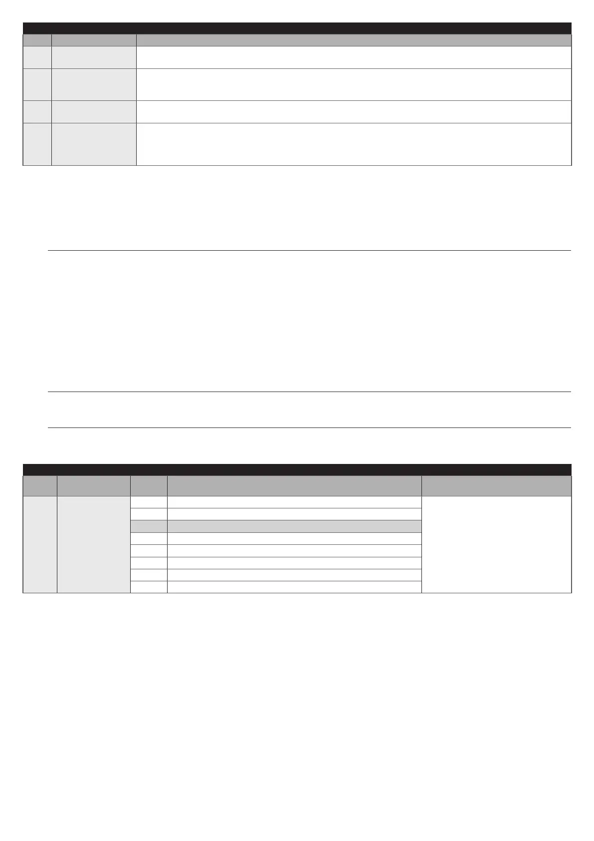
Table 7
LEVEL 2 FUNCTIONS (ADJUSTABLE PARAMETERS)
Entry
LED
Parameter
LED
(level)
Set value Description
L1 Pause Time
L1 5 seconds
Adjusts the pause time, in other
words, the time that elapses before
automatic re-closure. It is only
effective if the Close function is
enabled.
L2 15 seconds
L3 30 seconds
L4 45 seconds
L5 60 seconds
L6 80 seconds
L7 120 seconds
L8 180 seconds

 Loading...