ENGLISH – 19
Table 11
SIGNALS OF LED (L1..L4) (“FIGURE 21”)
Status Meaning Possible solution
LEDs L1 - L2
Slow ashing
Change in the number of
devices connected to the
“BlueBus” or learning of the
device not executed.
It is necessary to run the device learning procedure (refer to the “Learning
of connected devices” paragraph)
LEDs L3 - L4
Slow ashing
The positions of the
mechanical stops were
never learned or after the
mechanical stop learning
procedure, the dip-switch
conguration changed.
It is necessary to run the device learning procedure (refer to the “Learning
of connected devices” paragraph)
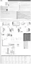
7.3 ANOMALY LOG
The control unit can display any anomalies that have occurred
in the last 8 manoeuvres (for example, the interruption of a ma-
noeuvre due to the intervention of a photocell or sensitive edge).
L1
L8
22
To check the list of anomalies:
1. press and hold the
g
button for roughly 3 sec-
onds
2. release the
g
button when the “L1” LED starts
ashing
3. press and release the
f
or
h
button to
shift ashing of the LED to “L8” (“Anomaly list” parameter)
4. keep the
g
button pressed down (it must be kept
pressed throughout phases 5 and 6)
5. wait roughly 3 seconds, after which LED “L1” – corre-
sponding to the outcome of the last manoeuvre – will light
up
6. press and hold the
f
or
h
button to se-
lect the desired manoeuvre: the corresponding LED will
emit the same number of ashes as those normally emit-
ted by the warning light after an anomaly (see “Table 9”)
7. release the
g
button.
FURTHER INFORMATION
(Accessories)
8
8 FURTHER DETAILS (Accessories)
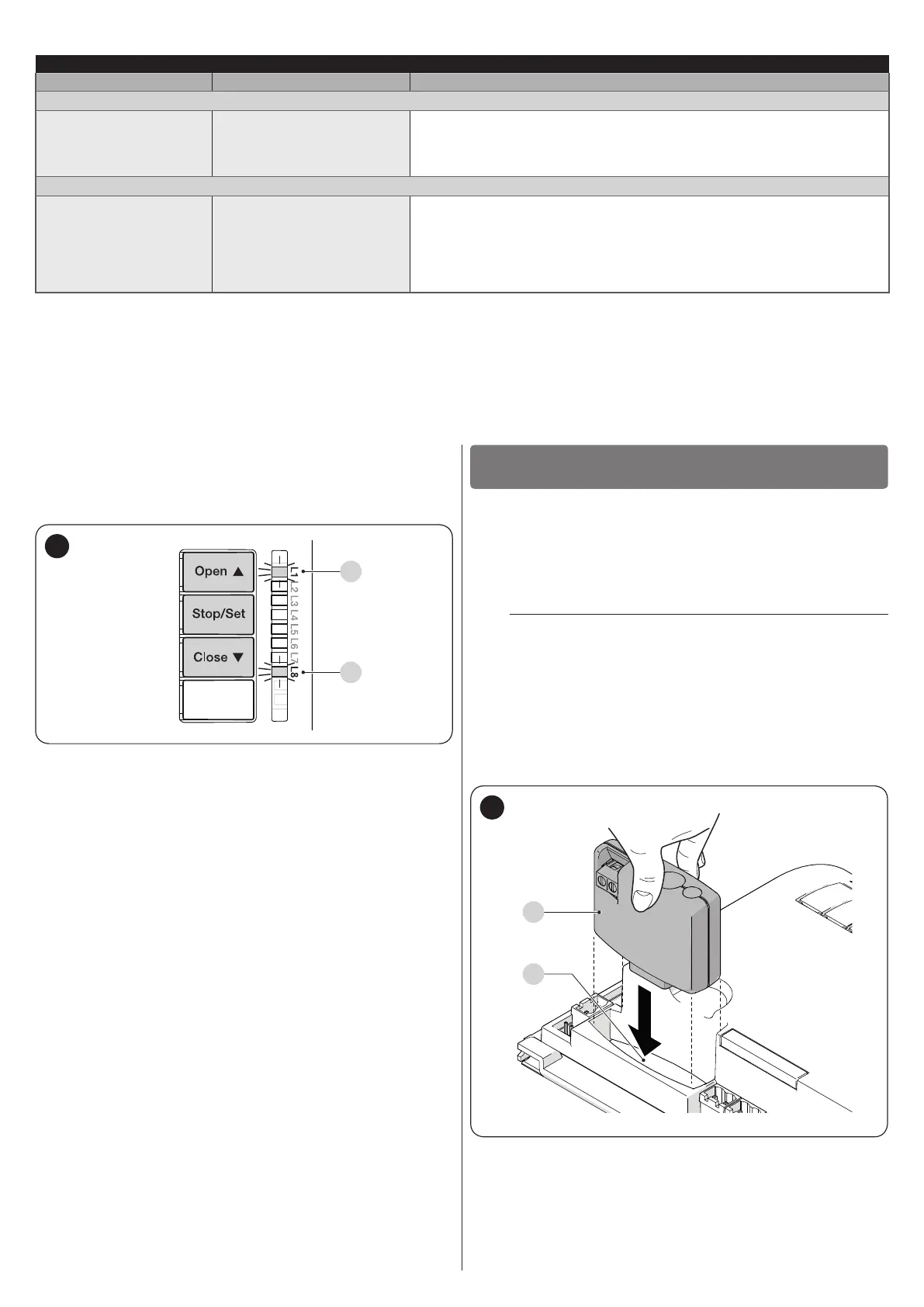
8.1 CONNECTING AN SM-TYPE RADIO RECEIVER
The control unit has a slot for mounting radio receivers with SM
connector (optional accessories), which can be used to remote-
ly control the control unit through transmitters that intervene on
the unit’s inputs.
f
Before installing a receiver, disconnect the power
supply to the control unit.
To install a receiver (“Figure 23”):
1. remove the cover of the control unit’s containment box
2. insert the receiver (A) in the appropriate slot (B) on the
control unit’s electronic board
3. put the cover of the control unit’s containment box back
on.
At this stage, the control unit can be powered again.
B
A
23

 Loading...