8
23
22
16
15
17
5423
RX
1
FOTO 2
TX
21
16
23
15
17
13
14
4231
RX
5
14
13
TX
21
FOTO 2
RX
54231
16
FOTO
TX
21
23
22
16
15
4231
RX
5
17
15
22
17
13
14
13
23
13
23
14
13
TX
21
FOTO
16
15
23
17
22
16
15
17
13
14
14
13
4231
RX
5
4231
RX
5
TX
21
TX
21
FOTO 2
FOTO
12 43251
5431221
17
22
23
16
15
RX
RXTX
TX
FOTO
FOTO 2
14
13
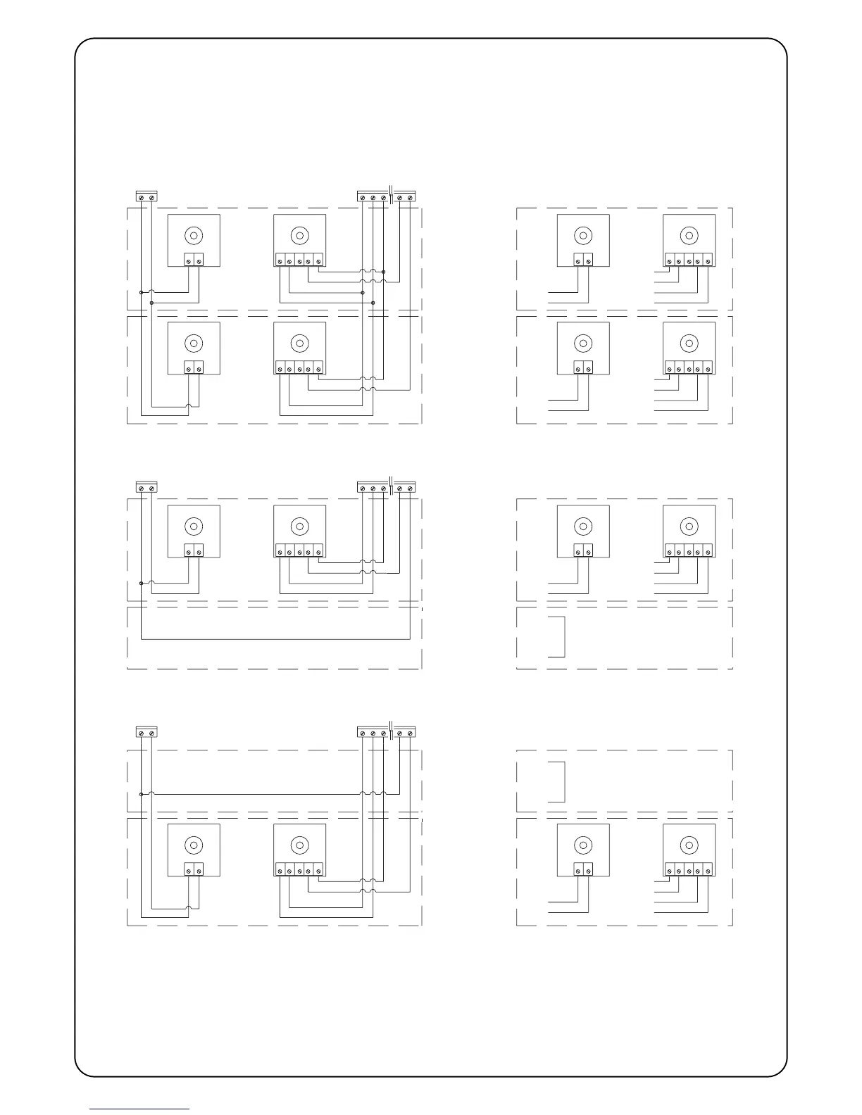
2.6) Phototest
The “Phototest” function is an excellent solution as regards the reli-
ability of safety devices and puts the control unit and photocell
assembly into category 2 as per UNI EN 954-1 standard (ed.
12/1998).
In order to implement this solution, connect the photocells as shown
in one of the figures 3A, 3B or 3C, and move Dip-Switch 7 to On
(activate “Phototest”).
Fig. 3A Shows how to connect Phototest with the Photo and Photo2 photocells
Fig. 3B Shows how to connect Phototest with just the Photo photocell
Fig. 3C Shows how to connect Phototest with just the Photo 2 photocell
When movement is required, the unit first check that all the receivers
involved give their consent, then it turns off the phototest output
after which it checks that all the receivers signal the fact by remov-
ing their consent; the phototest output is finally reactivated and the
consent of all the receivers is verified once more. If a faulty device or
a shorted cable, etc., is detected during the above sequence, the
manoeuvre is not carried out.
PHOTO
PHOTO 2
PHOTO
PHOTO PHOTO
PHOTO 2
PHOTO 2 PHOTO 2
 Loading...