28
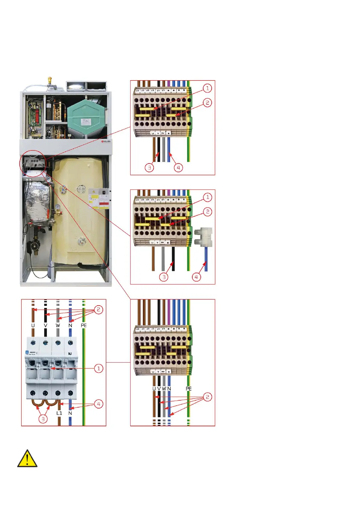
Change from 400V to 230V
The standard connection in the unit is 3x400V + N. In those countries or areas where this standard is not applicable, the unit can easily
be switched to either 3x230V or 1x230V.
The terminal block can be found in the control for AIR. Please refer to the wiring diagram enclosed with the unit.
3 x 400V + N
1. Jumper located in L1+L1+L1
(top clamping row)
2. Jumper located in N + zero
on the right (bottom clamping row)
3. Black wire located in V
(bottom clamping row)
4. Blue wire located in N
(bottom clamping row)
3 x 230V
1. Jumper located in L1 + L1 + L2
(top clamping row)
2. Jumper located in W + N
(bottom clamping row)
3. Black wire located in zero to the right of
N (lower clamping row)
4. Blue wire disconnected and
secured with crown sleeve
1 x 230V
1. In the panelboard there must be moun-
ted a 3x16A circuit breaker.
There must be 40A available before the
circuit breaker.
2. Wires are connected between the termi-
nal block and the circuit breaker:
U = brown, V = black,
W = gray, N = blue/zero.
3. Jumpers are mounted on the access side
of the circuit breaker from 1-2 and 2-3.
4. Brown (L1) is mounted in the third wire
inlet.
Blue/zero (N) is mounted in the fourth wire
inlet.
ATTENTION
The installer carries the responsibility for the electrical installation work.
 Loading...