Troubleshooting with RF shield removed
Introduction
The RF-shield should not be removed in order to replace single components on the RF block. This chapter
only assists in locating the faulty component for statistical purposes.
Voltage checking
Steps
1. Set up the main board in the module jig. The phone should be in local mode.
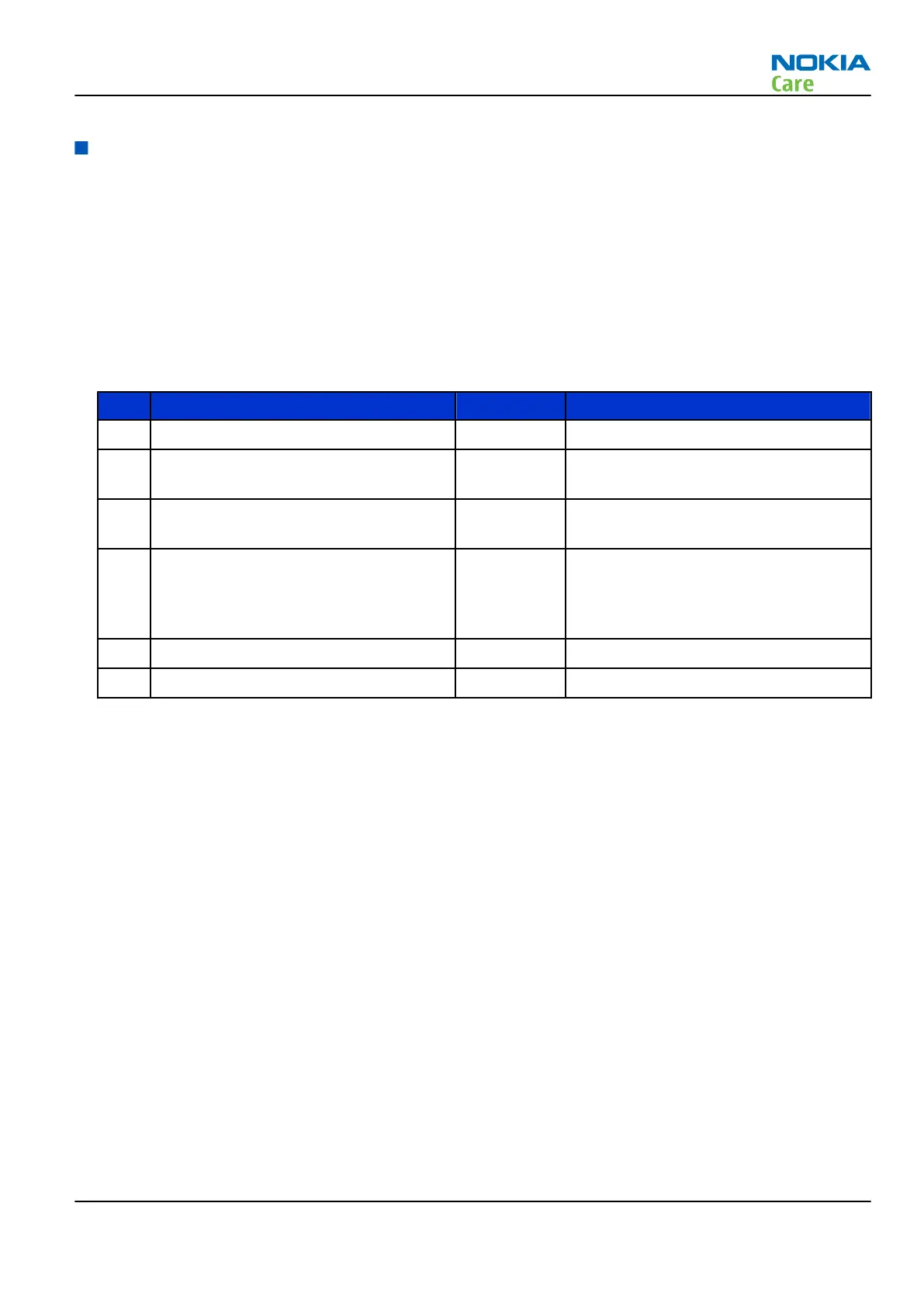
2. Check the following:
TP# Signal name Test point Voltage (all bands)
1 VCTCXO (G7500) supply C7501 2.5V
2 RFIC Vapaus (N7500) supply from DC/DC
converter
C7570 2.8V
3 TXFEM (N7520) supply from DC/DC
converter
C7521 1.3V-3.8V (only when transmitting and
depends on output power).
4 WCDMA PA (N7540) supply from DC/DC
converter
C7528 0.7V-3.1V (only when transmitting and
depends on output power). The value
will be 3.1V when settings as described
in the note below are used.
5 Vbat at WCDMA PA (N7540) C7512 3.7V (Vbattery)
6 Supply input to DC/DC conv C7527 3.7V (Vbattery)
Note: The result at TP4 should be 3.1V when using the same settings as shown in Figure Phoenix
WCDMA Tx control window in section WCDMA transmitter troubleshooting (page 4–19).
RM-509; RM-510; RM-511
RF Troubleshooting
Issue 2 COMPANY CONFIDENTIAL Page 4 –23
Copyright © 2009 Nokia. All rights reserved.
 Loading...