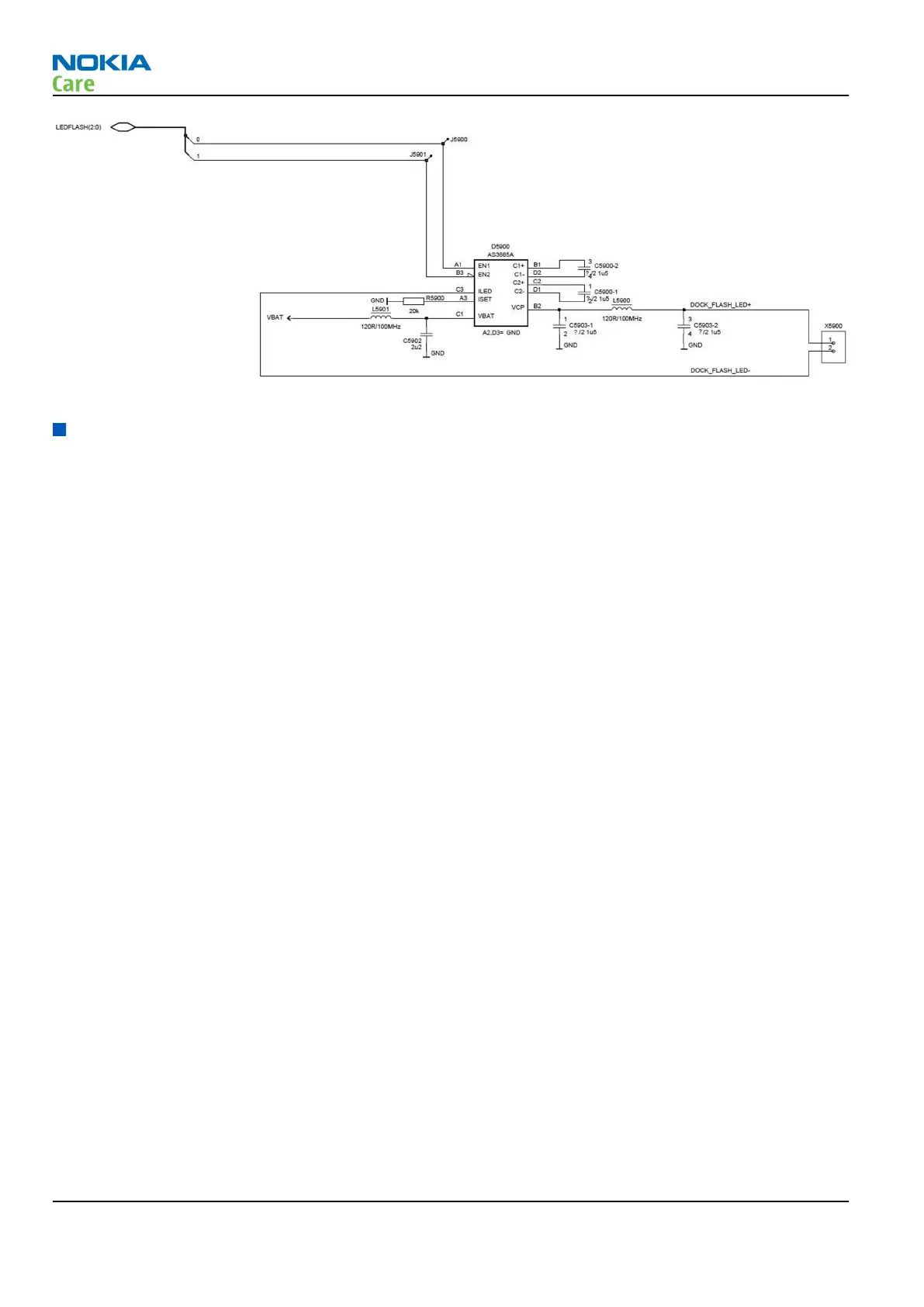
Figure 44 Camera flash LED driver design
Audio concept
Audio concept
The functional core of the audio hardware is built around two ASICs; Energy management ASIC N2200 and
digital ASIC D2800.
N2200 provides an interface for the transducers and the AV connector.
There are three audio transducers:
•
1 earpiece
•
1 IHF speaker
•
1 microphone module
N2200 also provides an output for the vibra motor.
All external audio accessories are connected to the specific audio connector.
The following block diagram illustrates the audio interface of the phone:
RM-509; RM-510; RM-511
System Module
Page 5 –20 COMPANY CONFIDENTIAL Issue 2
Copyright © 2009 Nokia. All rights reserved.
 Loading...