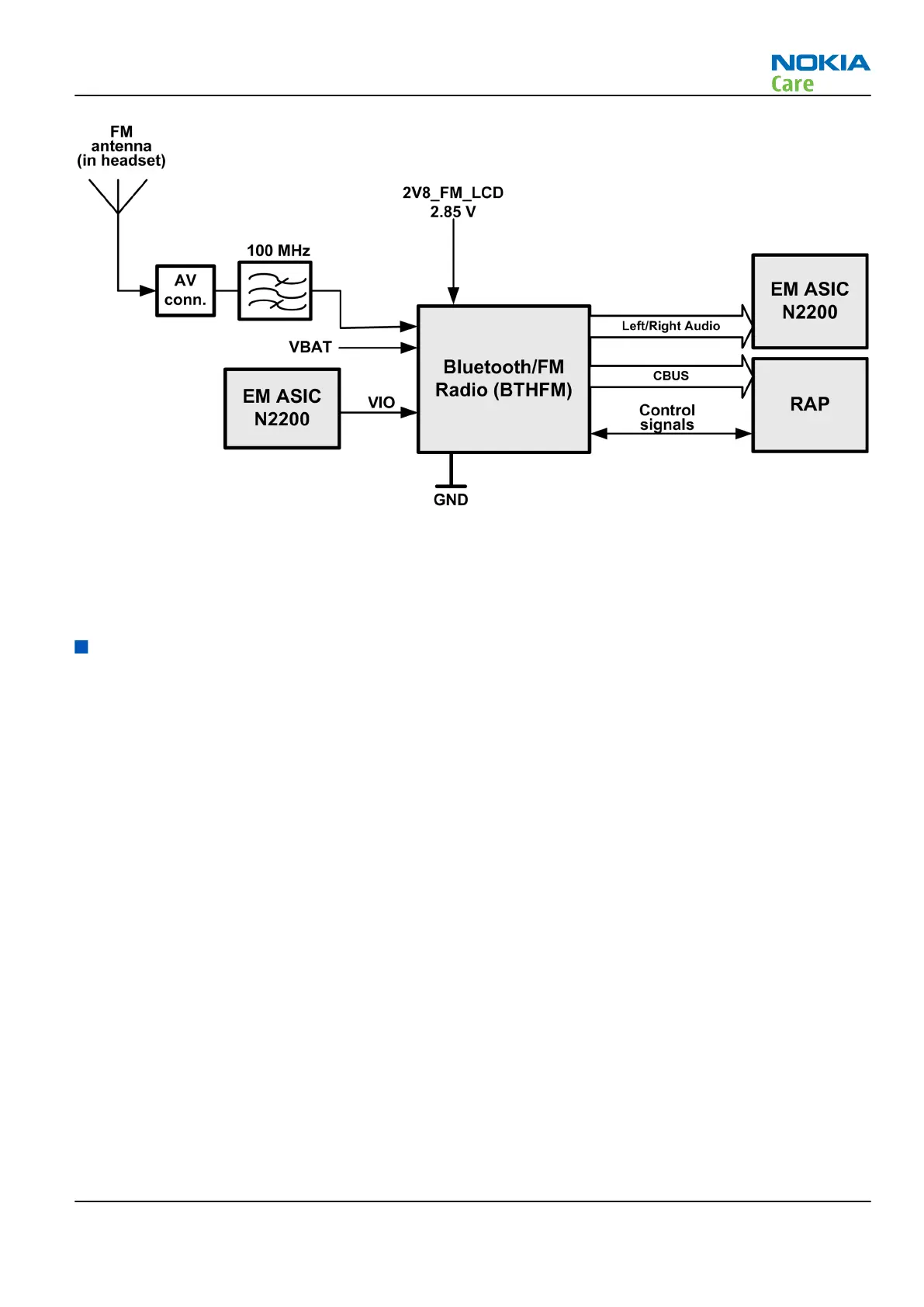
Figure 38 FM interface
The FM radio is an integrated circuit, controlled by MCU software through a serial bus interface. The wires of
the headset are used as poles of the antenna, and no other antenna is needed for FM radio reception.
In addition to the Bluetooth unit the FM radio is provided with LDO (low drop out) voltage 2V8_FM_LCD.
User interface
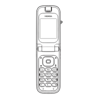
Display module
Display module
The display module consists of two different displays:
•
A main 2.2" 240 x 320 TFT display with 16M colors
•
A secondary 1.36" 128 x 160 TFT monochrome display.
The main display is only on when the phone is open, and the secondary display is only on when the phone
is closed.
The interconnection between the display module and RAP engine is implemented with a 24-pin board-to-
board connector. The display module is equipped with a driver with bi-directional 8-bit parallel interfaces.
If one of the displays is found to be faulty, the entire display module must be replaced.
RM-509; RM-510; RM-511
System Module
Issue 2 COMPANY CONFIDENTIAL Page 5 –15
Copyright © 2009 Nokia. All rights reserved.
 Loading...