AFP-3030 Installation Manual — P/N DOC-01-037:B 25/08/2016 6
Product Diagram System Overview
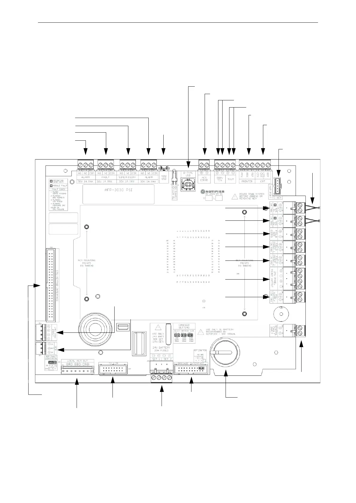
2.4 Product Diagram
The control panel electronics are contained on one printed circuit board assembly that holds the
central processing unit and power supply interface, collectively known as the CPU.
The following figure illustrates the location of the various connections, switches, jumpers and
LEDs on the circuit board. See Section 3 “Installation” for more details.
Figure 2.1 CPU Connections
Alarm Relay*
Fault Relay*
Supervisory Relay*
Alarm Relay*
Mini USB
Connection
ACS (power-limited, supervised)
Printer (isolated)
CTX/CRX
CRT-2 or Keltron printer
supervision
(TB5 CTX, REF No connection)
Lithium battery for backup
of on-board memory (See
Section 3.2.1
“Memory-Backup Battery”)
CPU Keypad
Interface
LCM Interface
NAC connection
ASM-02-056Modified.wmf
LCD2-80: TOut pins
B-Type USB Connection
Battery Power
Interface
Brigade Interface
(A.R.E. Connection)
LCD2-80: RDP pins
24 V DC Power from PSU
for Door Holders
†
NAC connection
24 V DC connection
Field ACM Communications Connection
Field Power connection
Field Power connection
Local ACM Out
General Fault Input
NUP connection for
HS-NCM network
communications
24 V Power
from PSU
Panel MCP
Connection
4K7 EOL
Resistors
* Relay may energise at power up and should not be used for Alarm Signalling Equipment. Alternative connections are available via
the Brigade Interface (A.R.E. Connection). See the A.R.E. Interface Board Installation Sheet for connection details.
†Door Holder Power must NOT be run directly to door holders in the field. This power must be fused
and must pass through a door holder relay to control when the doors are to be dropped.
 Loading...


