254
Wiring Section 5-3
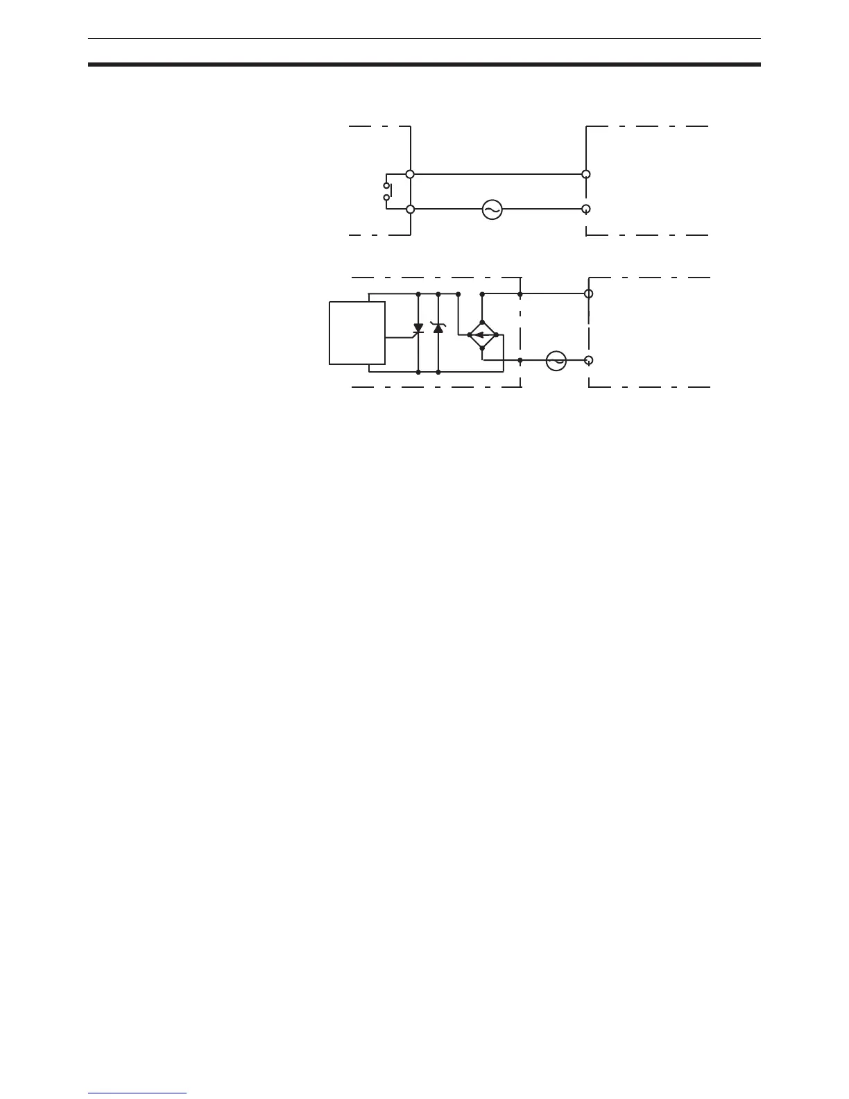
AC Input Units The following types of AC input devices can be connected.
Note When using a reed switch as the input contact for an AC Input Unit, use a
switch with an allowable current of 1 A or greater. If Reed switches with
smaller allowable currents are used, the contacts may fuse due to surge cur-
rents.
Precautions when
Connecting a Two-wire DC
Sensor
When using a two-wire sensor with a 12-V DC or 24-V DC input device, check
that the following conditions have been met. Failure to meet these conditions
may result in operating errors.
1,2,3... 1. Relation between voltage when the PLC is ON and the sensor residual
voltage:
V
ON
≤ V
CC
– V
R
2. Relation between voltage when the PLC is ON and sensor control output
(load current):
I
OUT
(min) ≤ I
ON
≤ I
OUT
(max.)
I
ON
= (V
CC
– V
R
– 1.5 [PLC internal residual voltage])/R
IN
When I
ON
is smaller than I
OUT
(min), connect a bleeder resistor R. The
bleeder resistor constant can be calculated as follows:
R
≤ (V
CC
– V
R
)/(I
OUT
(min.) – I
ON
)
Power W
≥ (V
CC
– V
R
)
2
/R × 4 [allowable margin]
3. Relation between current when the PLC is OFF and sensor leakage cur-
rent:
I
OFF
≥ I
leak
Connect a bleeder resistor if I
leak
is greater than I
OFF
. Use the following
equation to calculate the bleeder resistance constant.
COM
COM
IN AC
IN AC
Input Unit
Input Unit
Contact output
AC Switching
Proximity
switch
main
circuit
 Loading...


