6 Interrupts
6-8
CJ2M CPU Unit Pulse I/O Module User’s Manual
There are the following two ways to set whether to start the interrupt on OFF transitions or ON transi-
tions in the input.
• PLC Setup: The setting is always updated when the CPU Unit is changed from PROGRAM mode to
RUN mode.
• MSKS(690) instruction: The setting can be changed during operation.
The PV of a pulse output or high-speed counter can be latched when the interrupt input that starts the
interrupt task is received. The latched value is stored in the Auxiliary Area.
z Application Procedure
Set the terminals to use for interrupts as interrupt inputs.
(1) Select the PV to read.
Set the edge setting in the PLC Setup to specify whether to read the PV on an ON transition
or OFF transition.
(2) Execute the MSKS(690) instruction to enable the interrupt input.
Refer to page 6-11 for the settings for MSKS(690).
Additional Information
The power supply must be restarted after the PLC Setup is transferred in order to validate the
software latch settings.
Specifying to Detect ON or OFF
Using Software Latches
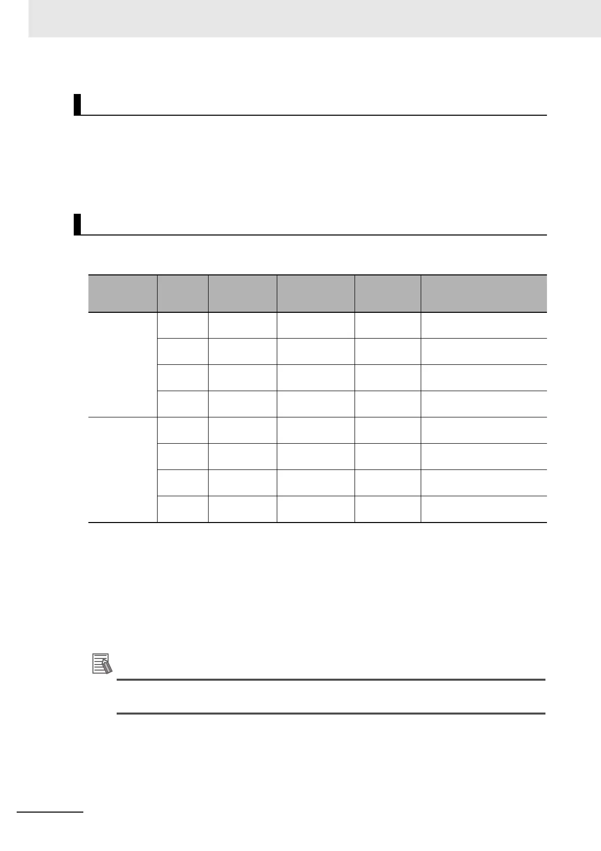
Pulse I/O
Module No.
Terminal
symbol
Correspond-
ing bit
address
Function
Interrupt task
number
Latched PV storage words
0 (on the right) IN00 CIO 2960.00 Interrupt input 0 140 A10145 (upper digits) and
A10144 (lower digits)
IN01 CIO 2960.01 Interrupt input 1 141 A10147 (upper digits) and
A10146 (lower digits)
IN02 CIO 2960.02 Interrupt input 2 142 A10149 (upper digits) and
A10148 (lower digits)
IN03 CIO 2960.03 Interrupt input 3 143 A10151 (upper digits) and
A10150 (lower digits)
1 (on the left) IN10 CIO 2962.00 Interrupt input 4 144 A10153 (upper digits) and
A10152 (lower digits)
IN11 CIO 2962.01 Interrupt input 5 145 A10155 (upper digits) and
A10154 (lower digits)
IN12 CIO 2962.02 Interrupt input 6 146 A10157 (upper digits) and
A10156 (lower digits)
IN13 CIO 2962.03 Interrupt input 7 147 A10159 (upper digits) and
A10158 (lower digits)

 Loading...


