5-7
5 Quick-response Inputs
CJ2M CPU Unit Pulse I/O Module User’s Manual
5-4 Creating Ladder Programs
5
5-3-1 Connector Pin Assignments
5-4 Creating Ladder Programs
Pulse inputs shorter than the cycle time can be read in the CPU Unit I/O memory using normal instruc-
tions by selecting Quick-response Input for the input terminal in the PLC Setup.
The status of CIO 2960.00 to CIO 2960.03 and CIO 2962.00 to CIO 2962.03 can be read using instruc-
tions such as the LD instruction.
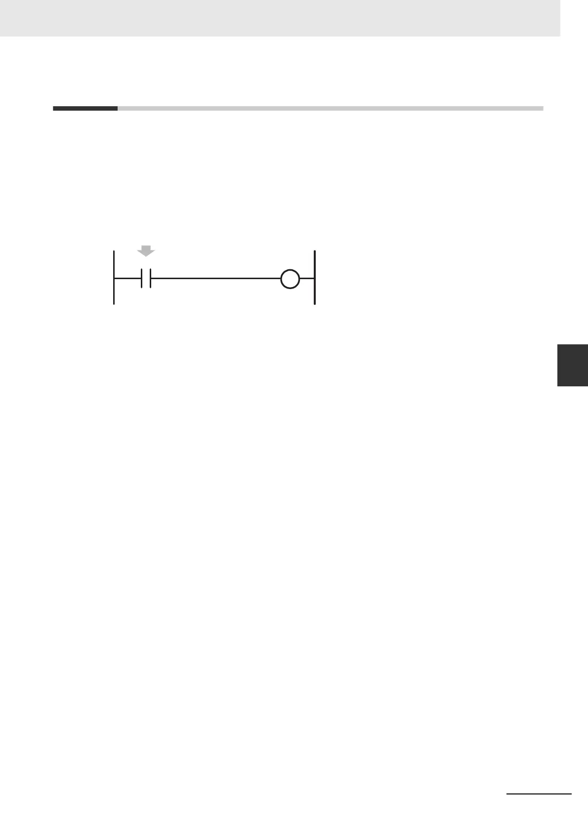
Example: Setting IN02 to Quick-response Input in the PLC Setup
• The minimum pulse width (ON time) that can be read for a quick-response input is 30 µs.
• The status of the input that is stored in the I/O memory for a short input will be cleared during the next
I/O refresh period.
2960.02
Even if the signal that is input to input terminal 02 is shorter than
the cycle time, the signal will be latched in one cycle and the
status will be stored in CIO 2960.02.

 Loading...


