
Do you have a question about the Omron CJ2M-CPU Series and is the answer not in the manual?
| Power Supply | 24 VDC |
|---|---|
| Number of Instructions | Over 400 instructions |
| Model | CJ2M-CPU11, CJ2M-CPU12, CJ2M-CPU13, CJ2M-CPU14, CJ2M-CPU15 |
| Program Capacity | 5K steps to 60K steps |
| I/O Capacity | Up to 2, 560 points |
| Communication Ports | Ethernet, USB, RS-232C |
| Execution Time | 0.04 µs per basic instruction |
| Operating Temperature | 0 to 55°C |
| Position Control | Supported |
| High-speed Counter | 100 kHz max. |
| Pulse Output | 100 kHz max. |
| Maximum Units | 40 units |
| Storage Temperature | -20 to 75°C |
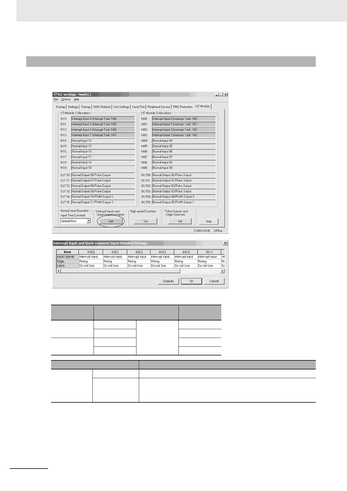
| Interrupt Inputs | Supported |


