5-3
5 Quick-response Inputs
CJ2M CPU Unit Pulse I/O Module User’s Manual
5-2 Application Procedure
5
5-2-1 PLC Setup
5-2 Application Procedure
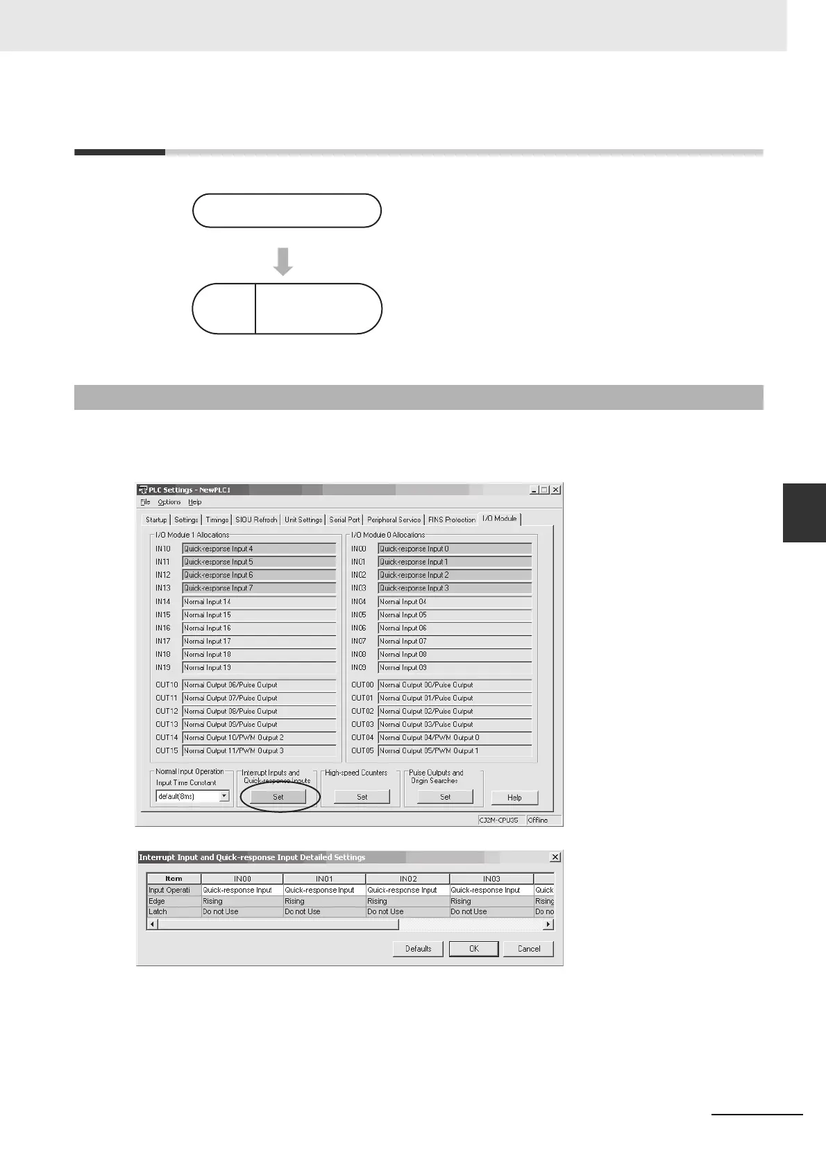
Click the Set Button in the Interrupt Inputs and Quick-response Inputs Area on the I/O Module Tab Page
of the PLC Setup. Select Quick-response Input for the input operation in the Interrupt Input and Quick-
response Input Detailed Settings Dialog Box.
1
• Select Quick-response Input in the Interrupt Input and
Quick-response Input Detailed Settings Dialog Box
that is accessed from the I/O Module Tab Page of the
PLC Setup using the CX-Programmer.
• IN00 to IN03 and IN10 to IN13 can be used for quick-
response inputs.
2
Read bit status using the LD instruction or other instruc-
tions.
5-2-1 PLC Setup
PLC Setup
Create
ladder
program.
Cyclic task or
interrupt task

 Loading...


