3 I/O Specifications and Wiring for Pulse I/O Modules
3-8
CJ2M CPU Unit Pulse I/O Module User’s Manual
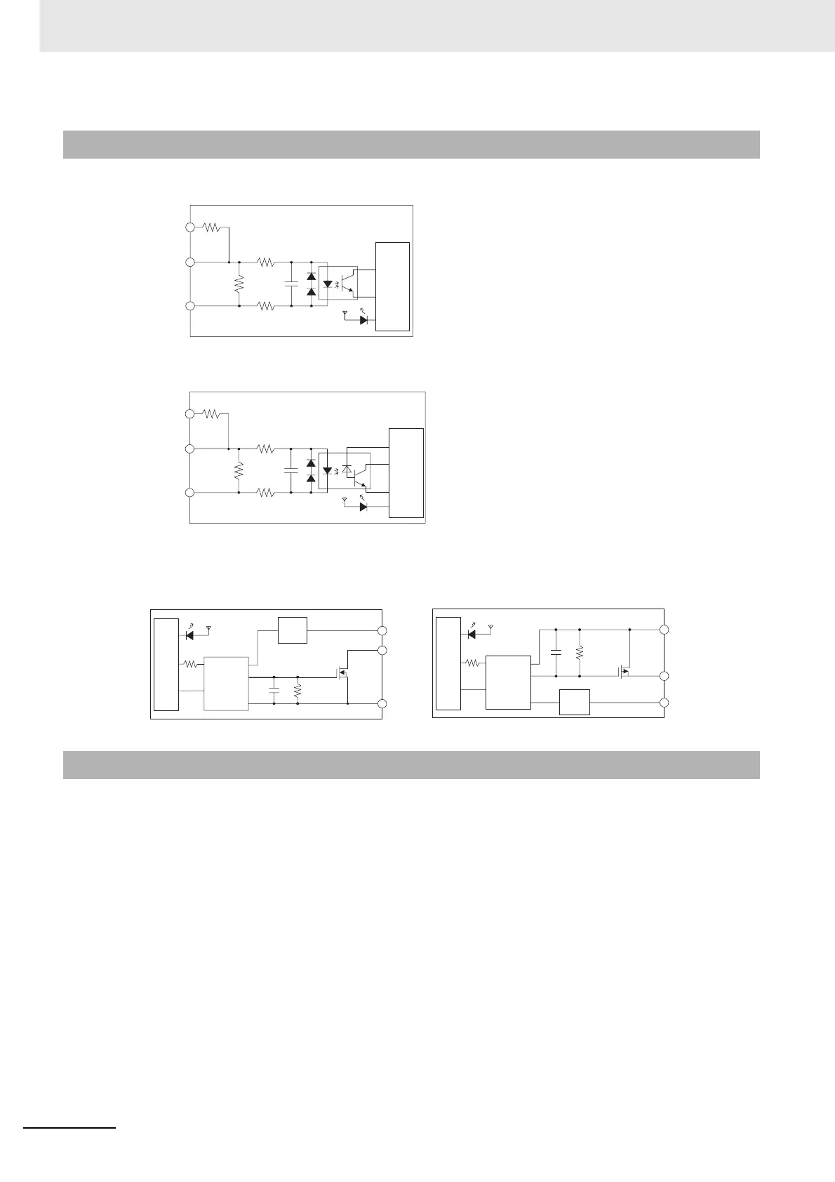
z Input Circuits (IN00 to IN05 and IN10 to IN15)
z Input Circuits (IN06 to IN09 and IN16 to IN19)
z Output Circuits (OUT00 to OUT05 and OUT10 to OUT15)
There are the following three methods for wiring a Pulse I/O Module.
• Using Connector-Terminal Block Conversion Units
Connector-Terminal Block Conversion Units are used when using normal I/O, quick-response
inputs, interrupt inputs, PWM outputs, or pulse outputs to stepping motors or other manufacturer's
Servo Drives.
• Using Servo Relay Units
Servo Relay Units are used when using OMRON's Servo Drives.
• Directly Connecting a Self-made Cable with a Connector
A self-made cable with a Connector can be used to directly connect the I/O.
3-2-2 I/O Circuit Configurations
• Sinking-type I/O Module (CJ2M-MD211) • Sourcing-type I/O Module (CJ2M-MD212)
3-2-3 Wiring
24 V
LD+
0 V/LD−
100 Ω
100 Ω
3.6 kΩ
Internal circuits
24 V
LD+
0 V/LD−
100 Ω
100 Ω
4.0 kΩ
Internal circuits
OUT
COM
+V
Internal circuits
Isolation
circuit
Rated
voltage
circuit
COM
−V
OUT
Internal circuits
Isolation
circuit
Rated
voltage
circuit

 Loading...


