4-11
4 Normal I/O
CJ2M CPU Unit Pulse I/O Module User’s Manual
4-3 Wiring
4
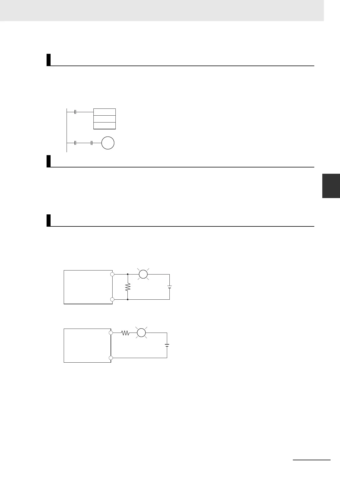
4-3-2 Wiring Examples
In this example, the sensor's power supply voltage is used as the input to CIO 0.00. A 100-ms timer
delay (the time required for an OMRON Proximity Sensor to stabilize) is created in the program.
After the Completion Flag for the timer turns ON, the sensor input on input bit CIO 0.01 will cause
output bit CIO 1.00 to turn ON.
z Output Short Protection
If a load connected to the output terminals is short-circuited, output components and the printed cir-
cuit boards may be damaged. To guard against this, incorporate a fuse in the external circuit. Use a
fuse with a capacity of about twice the rated output.
When switching a load with a high inrush current, such as an incandescent light bulb, there is a risk of
damaging the output transistor. Use either of the following methods to reduce the inrush current.
Programming Example
Output Wiring Precautions
Precautions on Inrush Current
TIM
0
#1
0.01T0
0.00
1.00
OUT
R
COM
L
+
OUT
R
COM
L
+
Method 1
Method 2
Output in Pulse I/O
Module
This method draws a dark current that is approximately
one-third of the rated value of the light bulb.
This method uses a limiting resistor.
Output in Pulse I/O
Module

 Loading...


