8 Pulse Outputs
8-46
CJ2M CPU Unit Pulse I/O Module User’s Manual
The operation mode parameter specifies the I/O signals that are used in the origin search.
*1 There are stepping motor drives that are equipped with a positioning completed signal like a Servo Drive.
Operation modes 1 and 2 can be used with these stepping motor drives.
*2 If not using the proximity input is set, only the origin input signal is used to perform the origin search.
8-5-5 Origin Search Operations
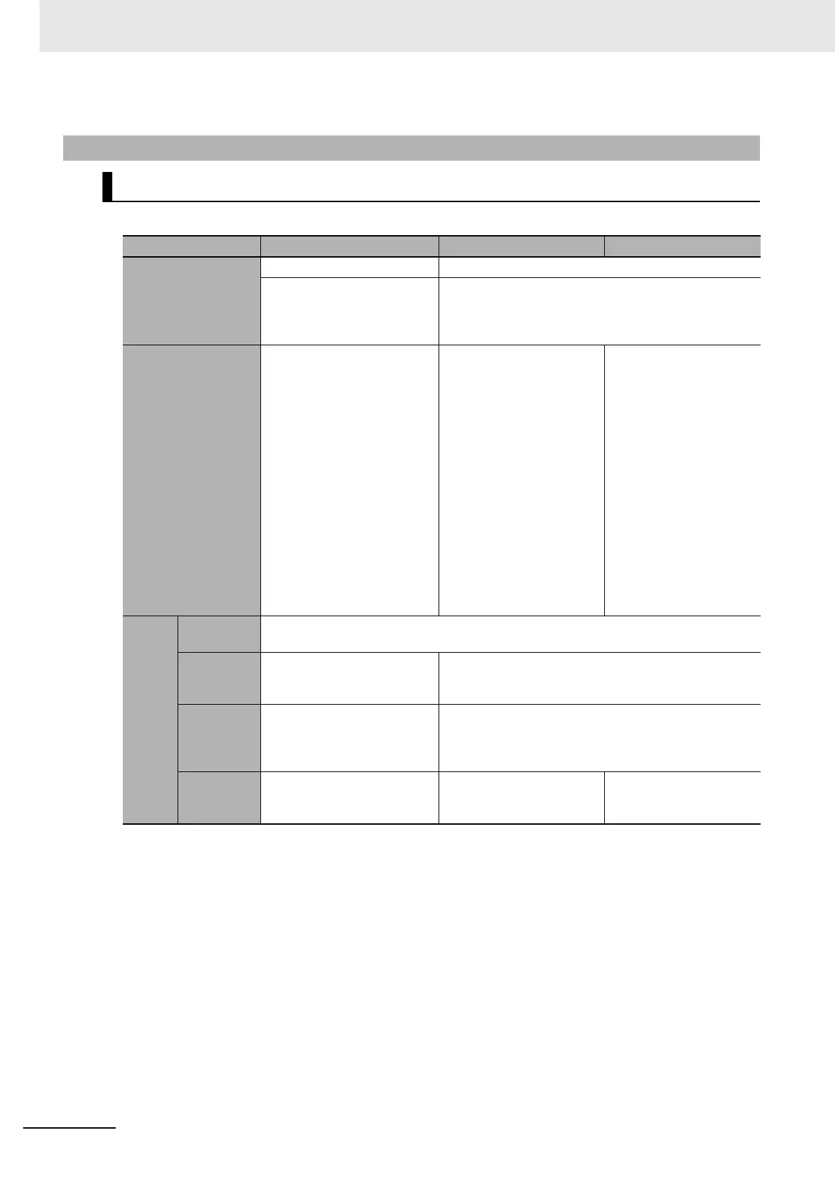
Operation Mode Settings and Operation
Operation Mode Operation mode 0 Operation mode 1 Operation mode 2
Applicable Servo
Drive
Stepping motor driver*1 Servo Drive
Two sensors, an origin prox-
imity sensor and an origin
sensor*2 are used to execute
an origin search.
An origin proximity sensor and the phase-Z signal from
a Servo Drive are used to execute an origin search.
Operation
• Movement is decelerated
when the origin proximity
input is received and the
search is completed on the
origin input.
• If the origin signal is
received while decelerating
for the proximity input, and
origin signal error will occur
and movement will deceler-
ate to a stop. (error code
2002)
• After decelerating for the
origin proximity input,
movement stops on the
phase-Z input from the
Servo Drive. Here, the
error counter reset output
is output to the Servo
Drive to complete the
search.
• Phase-Z inputs are
ignored during decelera-
tion for the proximity
input.
• After decelerating for
the origin proximity
input, movement stops
on the phase-Z input
from the Servo Drive.
Here, the error counter
reset output is output to
the Servo Drive and the
search is completed
when the positioning
completed input is
received from the Servo
Drive.
• Phase-Z inputs are
ignored during deceler-
ation for the proximity
input.
I/O sig-
nals
Origin prox-
imity input
Connect to a position detection sensor (e.g., photoelectric or proximity sensor).
Origin input
Connect to a position detec-
tion sensor (e.g., photoelec-
tric or proximity sensor).
Connect to the phase-Z output signal from the Servo
Drive.
Error
counter
reset out-
put
Not used. Connect to the error counter reset input of the Servo
Drive.
Positioning
completed
input
Not used. Not used. Connect to the position-
ing completed signal out-
put from the Servo Drive.