8-29
8 Pulse Outputs
CJ2M CPU Unit Pulse I/O Module User’s Manual
8-2 Position Control
8
8-2-2 Relative Positioning and Absolute
Positioning
• When the origin has been defined, the system operates using absolute coordinates.
Refer to 8-5-1 Origin Searches for details on origin searches.
z Relationship between the Coordinate System and Pulse Specifications
The following table shows the pulse output operation for the four possible combinations of the coor-
dinate systems (absolute or relative) and the pulse output (absolute or relative) specified when the
PULS(886) or PLS2(887) instruction is executed.
Conditions
Origin has been
defined by an origin
search
Origin has been defined by
executing the INI(880)
instruction to change the
PV
Origin is undefined (Origin
search has not been performed
and PV has not been changed
with the INI(880) instruction.)
Coordinate sys-
tem of pulse
output PV
Absolute coordinate system Relative coordinate system
Pulse output
specified in
PULS(886) or
PLS2(887)
Relative coordinate system Absolute coordinate system
Origin not defined
(The No-origin Flag will be ON.)
Origin defined
(The No-origin Flag will be OFF.)
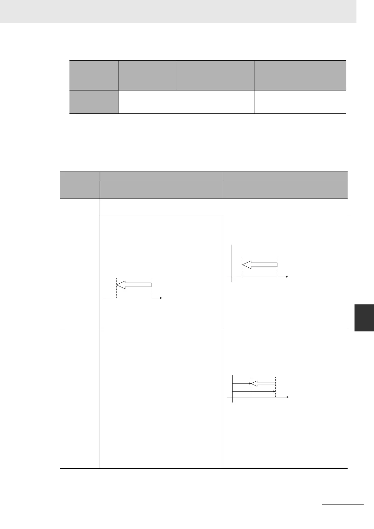
Relative pulses
specified
Positions the system to another position relative to the present position.
Number of movement pulses = Number of pulses setting
The pulse output PV after instruction execution =
Number of movement pulses = Number of pulses set-
ting
The pulse output PV is reset to 0 just before pulses
are output. After that, the specified number of pulses
is output.
The following example shows the number of CCW
pulses setting = 100 counterclockwise.
Pulse output PV range: 8000 0000 to 7FFF FFFF hex
Number of pulses setting range: 0000 0000 to 7FFF
FFFF hex
The pulse output PV after instruction execution = PV
+ Number of movement pulses.
The following example shows the number of pulses
setting = 100 counterclockwise.
Pulse output PV range: 8000 0000 to 7FFF FFFF hex
Number of pulses setting range: 0000 0000 to 7FFF
FFFF hex
Absolute
pulses speci-
fied
Absolute pulses cannot be used when the origin loca-
tion is undefined, i.e., when the system is operating
with a relative coordinate system. An instruction exe-
cution error will occur.
Positions the system to an absolute position relative
to the origin. The number of movement pulses and
movement direction are calculated automatically from
the present position (pulse output PV) and target posi-
tion.
The following example is for a number of pulses set-
ting of +100.
Number of movement pulses = Number of pulses set-
ting − Pulse output PV when instruction is executed.
The movement direction is determined automatically.
Pulse output PV when instruction is executed = Num-
ber of pulses setting
Pulse output PV range:
8000 0000 to 7FFF FFFF hex
Number of pulses setting range:
8000 0000 to 7FFF FFFF hex
100
Number of pulses setting
= Number of movement pulses
Target position
Pulse Output PV
Present position = 0
0
100
Number of pulses setting
= Number of movement pulses
Target position Present position
Pulse output
PV
+
100
0
+
200
Target position =
Setting of number of pulses
Origin
Present position
Pulse output
PV

 Loading...


