4-4
Power Supply Wiring
4-4-1
Power Supply Connector Specifications
The power supply connectors used for the Motion Controller are as follows.
One power supply connector is included in the Motion Controller.
Model Manufacturer
MVSTBW 2.5/3-ST-5,08 (1792760) Phoenix Contact
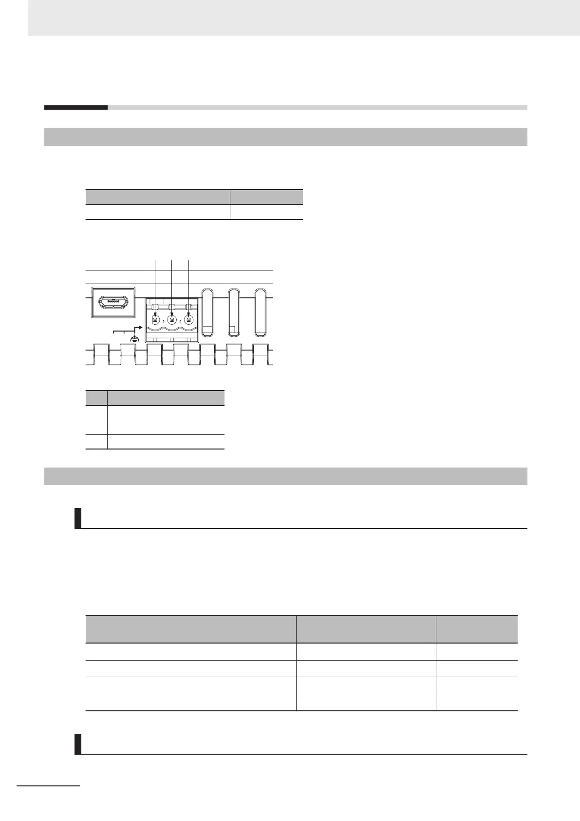
The following shows the pin assignment of the power supply connector used for the Motion Controller.
DC24V
INPUT
+V -V
DIAG.
1 2 3
Pin Description
1 24 VDC
2 0VDC
3 Function grounding terminal
4-4-2
Wiring the Power Supply Connector
Compatible Wires
Wires that can be connected to terminal holes of the power supply connector are bar terminals attach-
ed to twisted wires, twisted wires, and solid wires.
Select a power supply conductor by considering voltage drops and heat due to the cable length within
your installation environment.
The following table provides information about the conductors that are compatible with this connector.
Wire type Conductor cross-sectional area
Conductor length
(stripping length)
Solid wire
0.2 to 2.5mm
2
7mm
Twisted wire
0.2 to 2.5mm
2
7mm
Twisted wire with bar terminal, without plastic sleeve
0.25 to 2.5mm
2
7mm
Twisted wire with bar terminal, with plastic sleeve
0.25 to 2.5mm
2
7mm
Grounding
The type of grounding terminal onMotion Controlleris a functional ground terminal.
4 Mounting and Wiring
4-8
CK3E-series Programmable Multi-Axis Controller User’s Manual Hardware (I610)

 Loading...