5 Installation and Wiring
5-14
CP1E CPU Unit Hardware User’s Manual(W479)
5-3 Wiring
This section describes wiring methods for the CPU Unit.
Make sure that the power supply is OFF before beginning wiring.
• Wire a separate circuit for the power supply circuit so that there is no voltage drop from the inrush
current or startup current that flows when other equipment is turned ON.
• When several CP1E PLCs are being used, it is recommended to wire the PLCs on separate cir-
cuits to prevent a voltage drop from the inrush current or incorrect operation of the circuit breaker.
5-3-1 Wiring Procedure
1. Prepare the parts required for wiring. Prepare crimp terminals and cables for
wiring.
−
2. Connect the power supply terminals. Connect power supply to power supply
terminals L1 and L2/N.
Refer to 5-3-2 Wiring Power Supply
and Ground Lines.
3. Ground the ground terminal( ).
Ground to 100 Ω or less. Refer to 5-3-2 Wiring Power Supply
and Ground Lines.
4. Connect the input terminals. Connect sensors and switches to the
terminals.
Refer to 5-3-3 I/O Wiring.
5. Connect the output terminals. Connect loads to the terminals. Refer to 5-3-3 I/O Wiring.
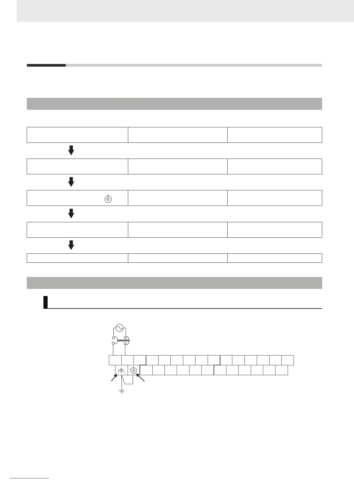
5-3-2 Wiring Power Supply and Ground Lines
Wiring AC Power Supply and Ground
MCCB
Ground to 100 Ω or less
Upper Terminal Block
S
R
GR: Protective ground terminal
LG: Functional ground terminal
L2/N COM 01 03 09 0105 07 11 03 05 07 09 11L1
00 02 04 06 08 10 00 02 04 06 08 10
100 to 240 VAC, 50/60 Hz

 Loading...


