3 Part Names and Functions
3-2
CP1E CPU Unit Hardware User’s Manual(W479)
3-1 CPU Units
This section describes the names of the CPU Unit parts and provides the I/O specifications and termi-
nal arrangements. Refer to A-1 Dimensions for the dimensions, A-2 Wiring Diagrams for the wiring dia-
grams.
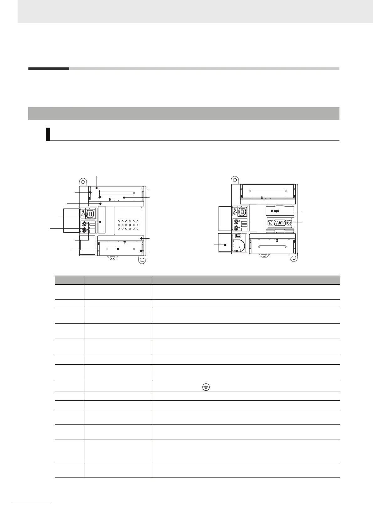
3-1-1 E10/14/20 or N14/20 CPU Units
Part Names and Functions
E-type CPU Unit
CP1E-E10D-
CP1E-E14/20DR-A
N-type CPU Unit
CP1E-N14/20D-
Number Name Function
Input terminal block This is the terminal block for inputs such as the power supply input and 24
VDC inputs.
Input indicators (yellow) Input status is displayed. An indicator will be ON when the input is ON.
Peripheral USB port Used to connect to a personal computer for programming and monitoring
by the CX-Programmer for CP1E.
Analog adjusters By turning an analog adjuster, it is possible to adjust the value of A642 or
A643 within a range of 0 to 255.
Operation indicators The CPU Unit’s operating status can be confirmed with this indicator.
Refer to CPU Unit Status Indicators (Page 3-3).
Output terminals Loads such as lamps, contactors, and solenoid valves can be connected.
Power supply input termi-
nals
Power of 100 to 240 VAC or 24 VDC can be supplied.
Ground terminal
Protective ground ( ): To prevent electric shock, ground to 100 Ω or less.
Input terminals Input devices such as switches and sensors can be connected.
Output indicators (yellow) Output status is displayed. An indicator will be ON when the output is ON.
Output terminal block This is the terminal block for outputs such as relay outputs and transistor
outputs.
Battery cover for N-type
CPU Units
A Battery can be installed by opening the cover. (The Battery is optional).
Built-in RS-232C com-
munications status indi-
cator
This indicator will be flashing when the built-in RS-232C port is in commu-
nication mode.
Built-in RS-232C port for
N-type CPU Units
By connecting a PT, the controlled system can be monitored and data can
be collected.
Input terminal block
Output terminal
block
Power supply input terminals
Input terminals
Output terminals
Ground terminal
Input indicators
Output indicators
Peripheral
USB port
Analog
adjusters
Operation indicators
Battery
cover
Built-in
RS-232C port
Built-in RS-232C
communications
status indicator

 Loading...


