3 Part Names and Functions
3-16
CP1E CPU Unit Hardware User’s Manual(W479)
The Serial Communication Port can be used for a CP1E N/NA-type CPU Unit.
Optional Serial Communication Board
How to mount an Option Board
When mounting an Option Board, first remove the slot cover.
Grasp both of the cover’s up/down lock levers at the same time to unlock the cover, and then pull the
cover out.
Then to mount the Option Board, check the alignment and firmly press it in until it snaps into place.
Precautions for Correct UsePrecautions for Correct Use
Always turn OFF the power supply to the PLC before mounting or removing an Option Board.
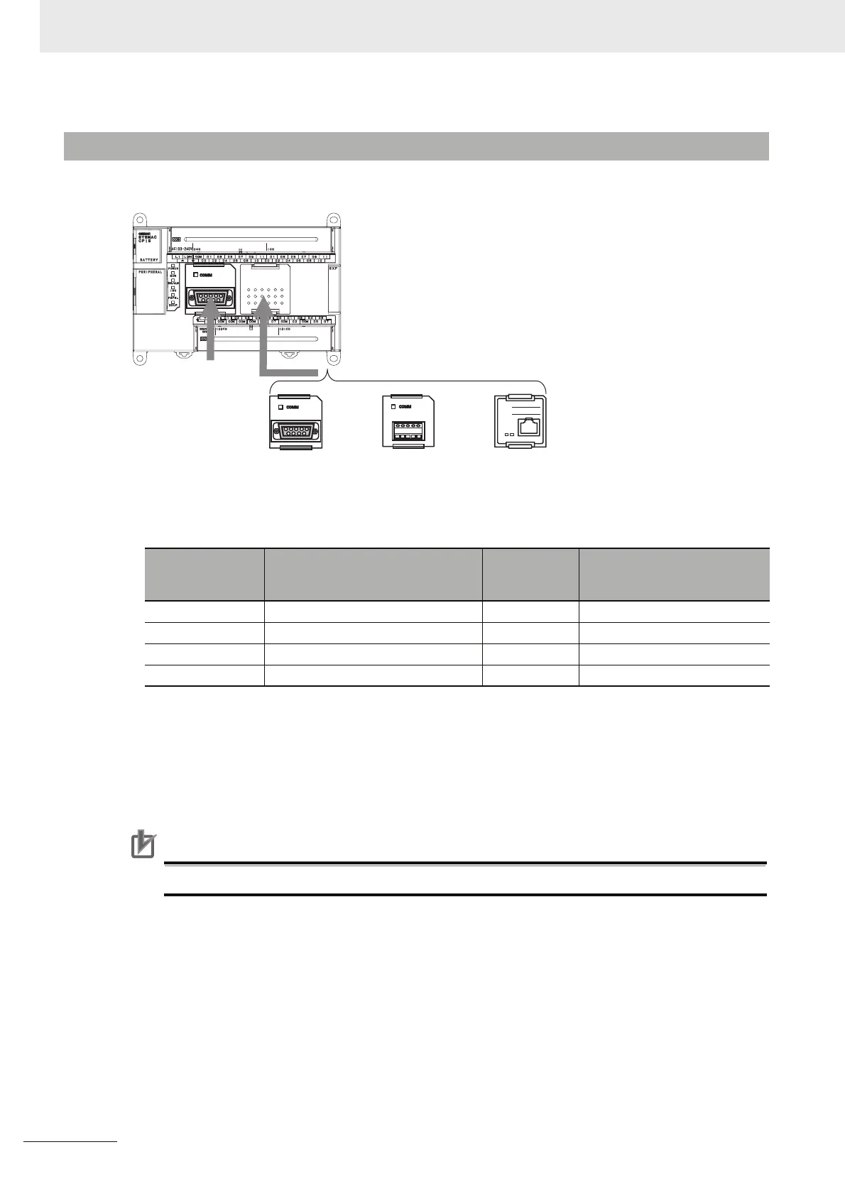
3-1-4 Optional Serial Communications Port for N/NA-type CPU Units
Model numbers Port
Maximum
transmission
distance
Connection method
CP1W-CIF01 One RS-232C port 15m Connector (D-sub, 9 pin female)
CP1W-CIF11 One RS-422A/485 port (not isolated) 50m Terminal block (using ferrules)
CP1W-CIF12 One RS-422A/485 port (isolated) 500m Terminal block (using ferrules)
CP1W-CIF41 One Ethernet port 100m Connector (RJ45, 8 pin modular)
CP1E N30/40/60
or NA20 CPU Unit
CP1W-CIF11/12
RS-422A/485 Option
Board
CP1W-CIF41
Ethernet Option
Board version 2.0
CP1W-CIF01
RS-232C Option
Board
Built-in
RS-232C port
+2#&&4'55
57$0'6/#5-
%1// '44
10BASE-T
100BASE-TX

 Loading...


