5-21
5 Installation and Wiring
CP1E CPU Unit Hardware User’s Manual(W479)
5-3 Wiring
5
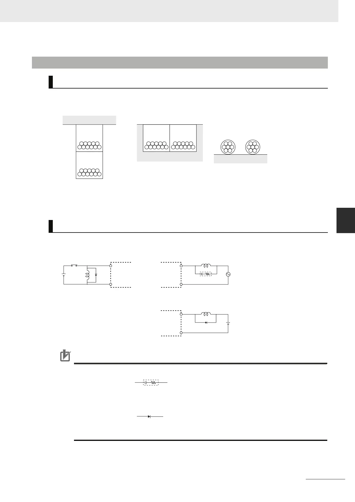
5-3-4 Wiring Safety and Noise Controls
Whenever possible, place I/O signal lines and power lines in separate ducts or conduits both inside and
outside of the control panel.
When wiring in the same duct, use shielded cables and connect the shields to the GR terminal to
reduce noise.
When an inductive load is connected to an I/O Unit, connect a surge protector or diode in parallel with
the load as shown below.
Precautions for Correct UsePrecautions for Correct Use
Use surge protectors and diodes with the following specifications.
5-3-4 Wiring Safety and Noise Controls
I/O Signal Wiring
Inductive Loads
Suspended ducts
Floor ducts Conduit
:I/O cables
:Power lines
L
IN
COM
DC input
Surge protector
OUT
COM
Diode
OUT
COM
Relay output
Relay output
Transistor output
L
+
Diode
Surge protector
Resistance
Capacitor
Voltage
: 50Ω
: 0.47μF
: 200V
Diode
Breakdown voltage
Mean rectification current
: 3 times load voltage
: 1 A

 Loading...


