EasyManua.ls Logo

Omron CP1E-ED User Manual

Omron CP1E-ED
262 pages
To Next Page IconTo Next Page
To Previous Page IconTo Previous Page
Page #200 background imageLoading...
Page #200 background image
8-45
8 Using Expansion Units and Expansion I/O Units
CP1E CPU Unit Hardware User’s Manual(W479)
8-4 Temperature Sensor Units
8
8-4-4 Flow of Operation
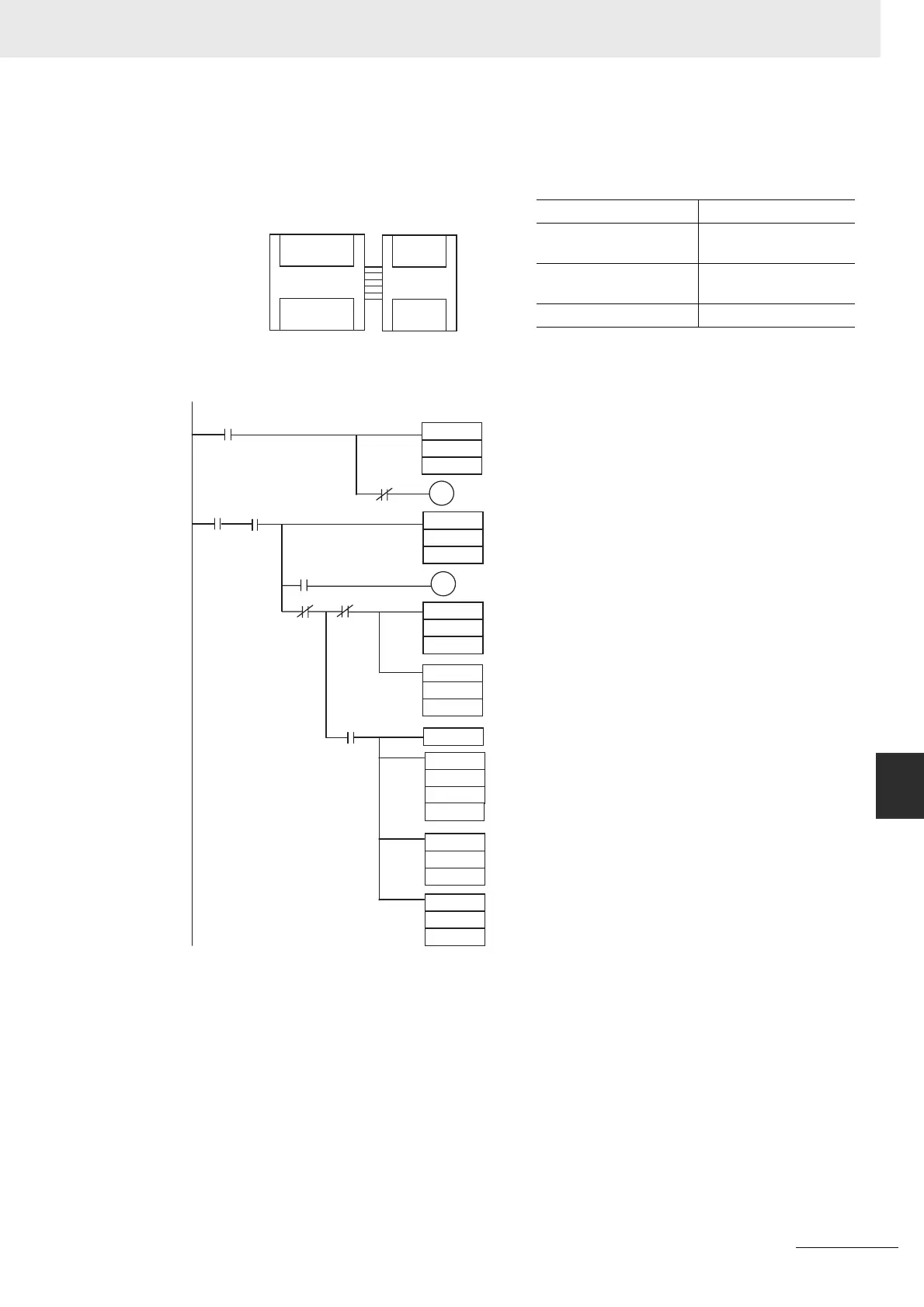
(b) The following programming example shows how to convert the data for tempera-
ture input 0 to BCD and store the result in D0 and D1. “#0001” is stored in D1
when the input data is a negative value. The following system configuration is
used.
(6) Programming with BCD Instruction
Temperature unit setting 0(°C)
Two-decimal-place
Mode
0 (normal)
Input range setting 1 (Pt100: -200.0 to
650.0°C)
Input 0 CIO 2
CP1E CPU Unit
CP1W-TS001/101
Temperature Sensor Unit
Inputs
Outputs
CIO 0
CIO 1
CIO 100
CIO 101
CIO 2
CIO 3
None
002
#7FFF
W0.00
CMP
W0.00
2
#7FFE
Always ON
P_On
CMP
Detects completion of input 0 initialization.
P_EQ
W0.01
2
D0
BCD
2.15
#0000
2
SBB
P_EQ
2.15
#0000
D1
MOV
CLC
D0
D0
D0
BCD
#0001
D1
MOV
Execution
condition
ON when input 0 has been initialized
Detects an open-circuit alarm or Unit
error by checking whether the error code
7FFF has been output
ON when an open-circuit alarm or Unit
error has been detected for input 0.
Stores positive BCD data in D0.
Stores #0000 in D1.
When input 0 converted value is negative
(#0000 minus two’s complement = actual
value)
Stores negative BCD data in D0.
Stores #0001 in D1 to indicate a
negative number.
P_EQ

Table of Contents

Question and Answer IconNeed help?

Do you have a question about the Omron CP1E-ED and is the answer not in the manual?

Omron CP1E-ED Specifications

General IconGeneral
ModelCP1E-ED
ManufacturerOmron
Operating Temperature0 to 55 °C
TypeProgrammable Logic Controller (PLC)
Power Supply100 to 240 VAC or 24 VDC
Output TypeRelay
Pulse Output1 channel (20kHz)
Expansion ModulesYes
Humidity10 to 90%
Vibration Resistance10 to 57 Hz
Shock Resistance147 m/s² X, Y, and Z directions 3 times each
Dimensions90 x 90 x
Communication Ports1 port (RS-232C)

Summary

Introduction

Safety Precautions

Definition of Precautionary Information

Explains the notation used for safety warnings, cautions, and important information.

Precautions for Safe Use

Power Supply

Safety guidelines related to power supply connection and handling.

Installation

Safety guidelines to follow during the physical installation of the unit.

Wiring

Safety guidelines to follow during the electrical wiring process.

Chapter 1 Overview and Specifications

1-2 Basic Operating Procedure

Chapter 3 Part Names and Functions

Chapter 4 Programming Device

4-1-2 CX-Programmer

Describes the CX-Programmer software for PLC programming and debugging.

Chapter 5 Installation and Wiring

5-1 Fail-safe Circuits

Details essential fail-safe circuits to be set up outside the CP1E.

5-3 Wiring

Describes the methods for wiring the CP1E CPU Unit and its components.

Chapter 6 Troubleshooting

6-1 Troubleshooting CPU Unit Errors

Provides steps and information for troubleshooting CPU Unit errors.

6-2 Troubleshooting Unit Errors

Guides users through troubleshooting errors in units other than the CPU Unit.

Chapter 7 Maintenance and Inspection

Related product manuals