EasyManua.ls Logo

Omron CPM2A - 11-2005 User Manual

Omron CPM2A - 11-2005
187 pages
To Next Page IconTo Next Page
To Previous Page IconTo Previous Page
Page #150 background imageLoading...
Page #150 background image
5-5SectionTroubleshooting Flowcharts
133
Type Meaning and appropriate responseMessage
B
IL-ILC ERR IL(02) and ILC(03) are not used in pairs. Check the
program before processing.
JMP-JME ERR JMP(04) and JME(05) are not used in pairs. Check the
program before processing.
SBN-RET ERR RET(93) has not been used properly or the relationship
between SBN(92) and RET(93) is not correct. Correct the
program.
C
COIL DUPL The same bit is being controlled (i.e., turned ON and/or
OFF) by more than one instruction (e.g., OUT, OUT NOT,
DIFU(13), DIFD(14), KEEP(11), SFT(10)). This error
occurs when the same number is used for the timer and
counter instructions. Although this is allowed for certain
instructions, check instruction requirements to confirm that
the program is correct or rewrite the program so that each
bit is controlled by only one instruction.
JMP UNDEFD JME(05) has been used with no JMP(04) with the same
jump number. Add a JMP(04) with the same number or
delete the JME(05) that is not being used.
SBS UNDEFD A subroutine exists that is not called by SBS(91). Program
a subroutine call in the proper place, or delete the
subroutine if it is not required.
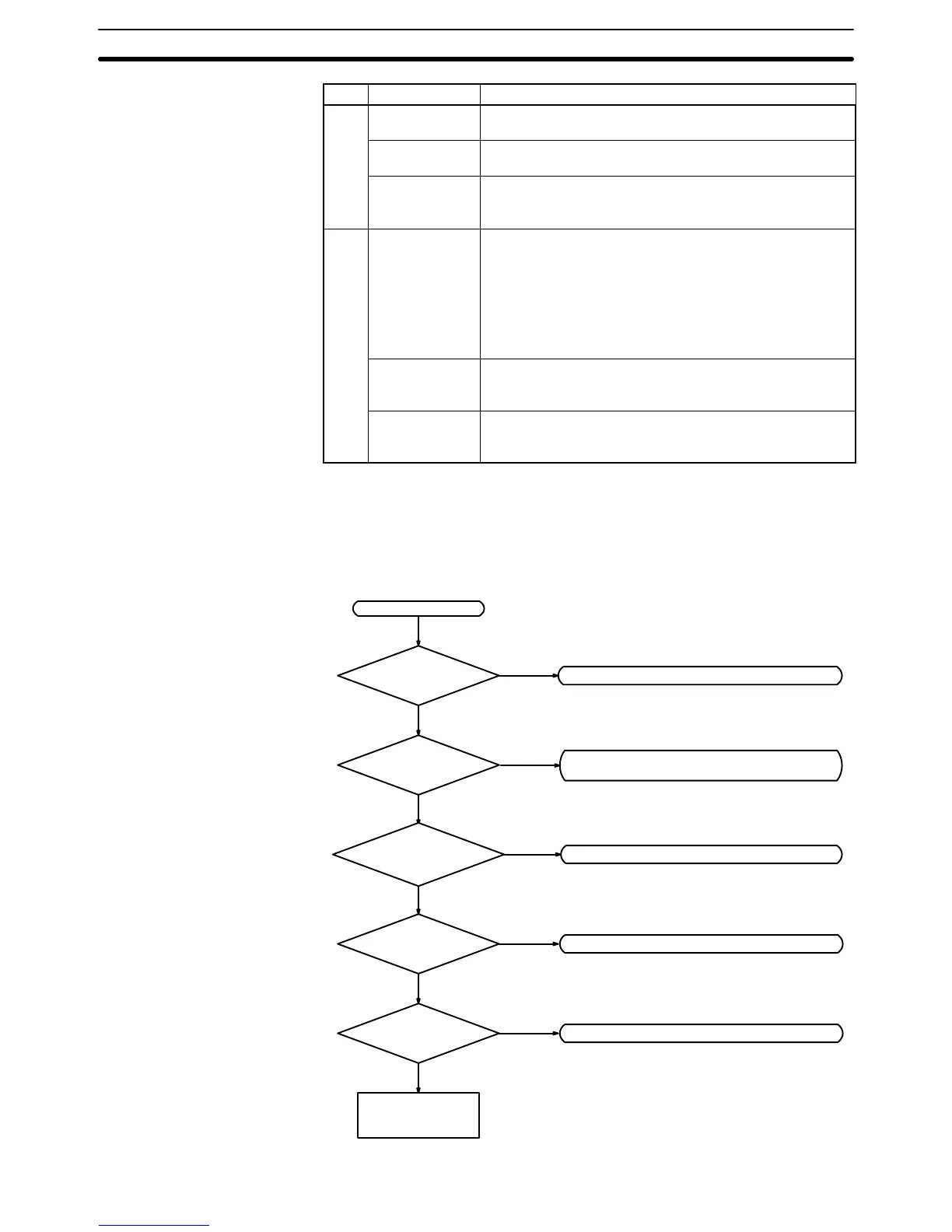
5-5 Troubleshooting Flowcharts
Use the following flowcharts to troubleshoot errors that occur during operation.
Main Check
Check for non-fatal errors. (See page 136.)
Error
Replace the CPU
Unit.
PWR indicator lit?
RUN indicator lit?
ERR/ALM indicator
flashing?
Is I/O sequence
normal?
Operating
environment normal?
Operation stopped. Check for fatal errors.
(See page 135.)
Check I/O. (See page 137.)
Check operating environment. (See page 139.)
Yes
Check power supply. (See page 134.)
No
No
No
No
Flashing
Yes
Yes
Not lit
Yes

Table of Contents

Question and Answer IconNeed help?

Do you have a question about the Omron CPM2A - 11-2005 and is the answer not in the manual?

Omron CPM2A - 11-2005 Specifications

General IconGeneral
CategoryController
ManufacturerOmron
Output TypeRelay
Input Voltage24 VDC
Supply Voltage100 to 240 VAC
Timer/Counter256
Communication PortRS-232
Operating Temperature0 to 55°C
Humidity10% to 90% RH (with no condensation)
Program Capacity2048 Steps

Summary

SECTION 1 Introduction

CPM2A Features and Functions

Describes the features and functions of the CPM2A PCs, covering basic and advanced capabilities.

SECTION 2 Unit Specifications and Components

Specifications

Presents detailed technical specifications for CPM2A CPU Units and expansion units.

SECTION 3 Installation and Wiring

Installing the CPM2A

Provides step-by-step instructions for physically installing the CPM2A CPU Unit and expansion units.

Wiring and Connections

Details the procedures for correctly wiring power supplies, I/O devices, and communication devices.

SECTION 4 Using a Programming Console

Programming Console Operations

Explains various operations and functions available when using a programming console with the CPM2A.

SECTION 5 Test Runs and Error Processing

Initial System Checks and Test Run Procedure

Outlines the procedures for initial system checks and performing test runs of the CPM2A.

Troubleshooting Flowcharts

Provides flowcharts to help diagnose and resolve operational errors and issues.

Related product manuals