!
66
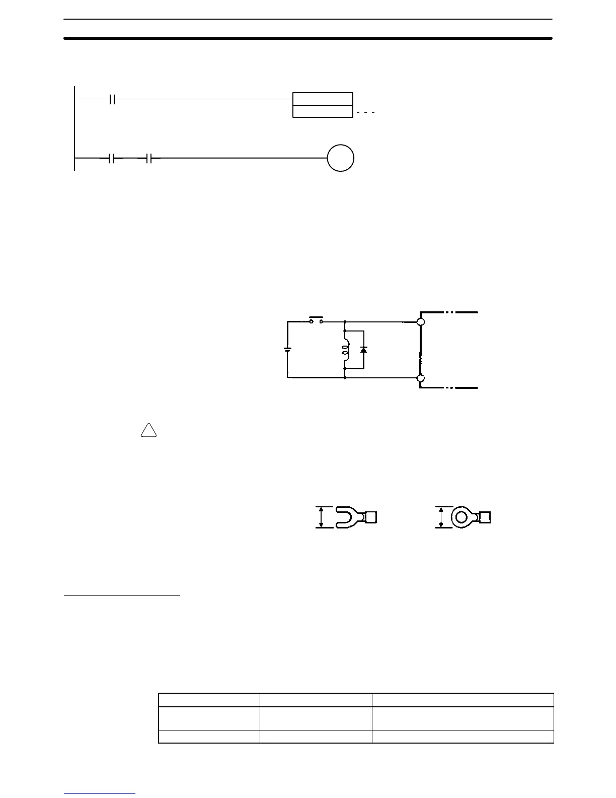
gram to delay accepting inputs from a sensor from when the sensor is turned ON
until the sensor reaches stable operation.
00000: Sensor power supply voltage detection
Time required for sensor to stabilize
(for OMRON Proximity Sensor): 100 ms
00001: Input from sensor
TIM 0000
#0002
00000
01000
TIM000 00001
Note The SV of TIM 000 can be set to #0001 (0.1 s) to achieve a delay time of 100 ms,
but the timer accuracy is 0 to 0.1 s, meaning that the timer’s Completion Flag
may turn ON immediately after the timer input. The SV must thus be set to #0002
(0.2 s) or higher to allow for timer accuracy.
Inductive Loads When connecting an inductive load to an input, connect a diode in parallel with
the load. The diode should satisfy the following requirements:
1, 2, 3... 1. Peak reverse-breakdown voltage must be at least 3 times the load voltage.
2. Average rectified current must be 1 A.
IN
COM
CPM2A
Diode
Crimp Terminals
Caution Always use crimp terminals for the CPM2A’s I/O lines or use solid wire (instead
of a stranded wire). Do not connect bare stranded wires directly to terminals.
Stray wire strands can short-circuit and cause a fire.
Use M3 crimp terminals and tighten the terminal screws to a torque of 0.5 N S m.
6.2 mm max. 6.2 mm max.
Fork terminal Ring terminal
The recommended wire size for solid wires is 0.4 to 1.2 mm (AWG26 to AWG18).
3-4-6 Output Wiring
Relay Output Wiring
Wire the outputs to the CPM2A’s CPU Unit and Expansion I/O Units as shown in
the following diagrams. Use crimp terminals or solid wires (not stranded wire) to
connect to the PC. The power supply output terminals can be used with a CPU
Unit with an AC power supply.
• Always use single wire or attach crimp terminals if a stranded wire is used.
• Don’t exceed the output capacity or the maximum common current. Refer to
2-1-3 I/O Specifications for details.
Item Relay outputs Transistor outputs, sinking or sourcing
Output capacity 2 A (250 VAC or 24 VDC) 01000 and 01001: 200 mA (30 VDC)
01002 and higher: 300 mA (30 VDC)
Max. common capacity 4 A/common 0.8 A/common
Wiring and Connections
Section 3-4

 Loading...


