!
!
48
3-1 Design Precautions
Observe the following precautions when designing a system incorporating a
CPM2A PC.
3-1-1 Power Supply Wiring
Separate the power supply wiring from the control system, CPM2A system, and
DC I/O system wiring. Separate the control circuits that supply power to the main
Unit from the main circuits using dedicated circuit protectors and fuses.
3-1-2 Power Supply Voltage
Caution Use the power supply voltages indicated in Section 2 Unit Specifications and
Components. Failure to adhere to the specifications may result in fire.
If the power supply voltage falls below 85% of the rated voltage, the CPM2A will
stop and all outputs will be turned OFF. If low voltage affects the equipment, etc.,
provide a protection circuit which shuts off the output until the supply voltage re-
turns to the rated value.
In places where power supply conditions are poor, take steps to ensure that
power is supplied at the rated voltage. Be sure to adhere to safety precautions,
such as providing breakers to prevent short circuits in external wiring.
When conducting any of the following operations, turn OFF the power to the PC.
Electrocution, product damage and malfunction may result.
• Connecting or disconnecting Expansion Units, Expansion I/O Units, and CPU
Units.
• Assembling Units
• Connecting cables and wiring.
3-1-3 Interlock and Limit Circuits
WARNING Emergency stop circuits, interlock circuits, limit circuits, and similar safety
measures must be provided in external control circuits (i.e., not in the
Programmable Controller) to ensure safety in the system if an abnormality
occurs due to malfunction of the PC or another external factor affecting the PC
operation. Not providing proper safety measures may result in serious
accidents.
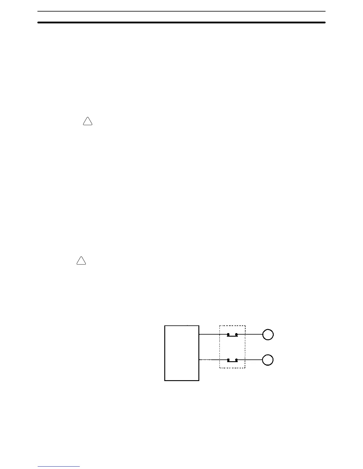
The following diagram shows an example of an interlock circuit.
Interlock Circuit
Motor forward
Motor reverse
CPM2A
01005
01006
MC1
MC2
MC2
MC1
In the interlock circuit above, MC1 and MC2 can’t be ON at the same time even if
CPM2A outputs 01005 and 01006 are both ON (an incorrect PC operation).
3-2 Selecting an Installation Site
The CPM2A is resistant to harsh conditions and highly reliable, but installing the
PC in a favorable site will maximize its reliability and operating lifetime.
Selecting an Installation Site
Section 3-2

 Loading...


