50
Accessibility Ensure that the CPM2A can be accessed for normal operation and mainte-
nance.
• Provide a clear path to the CPM2A for operation and maintenance. High-volt-
age equipment or power lines could be dangerous if they are in the way during
routine operations.
• The PC will be easiest to access if the panel or cabinet is installed about 3 to 5
feet above the floor.
3-3 Installing the CPM2A
This section describes how to install the CPM2A and connect Expansion Units
and Expansion I/O Units. Refer to Appendix B for diagrams showing the dimen-
sions of the Units.
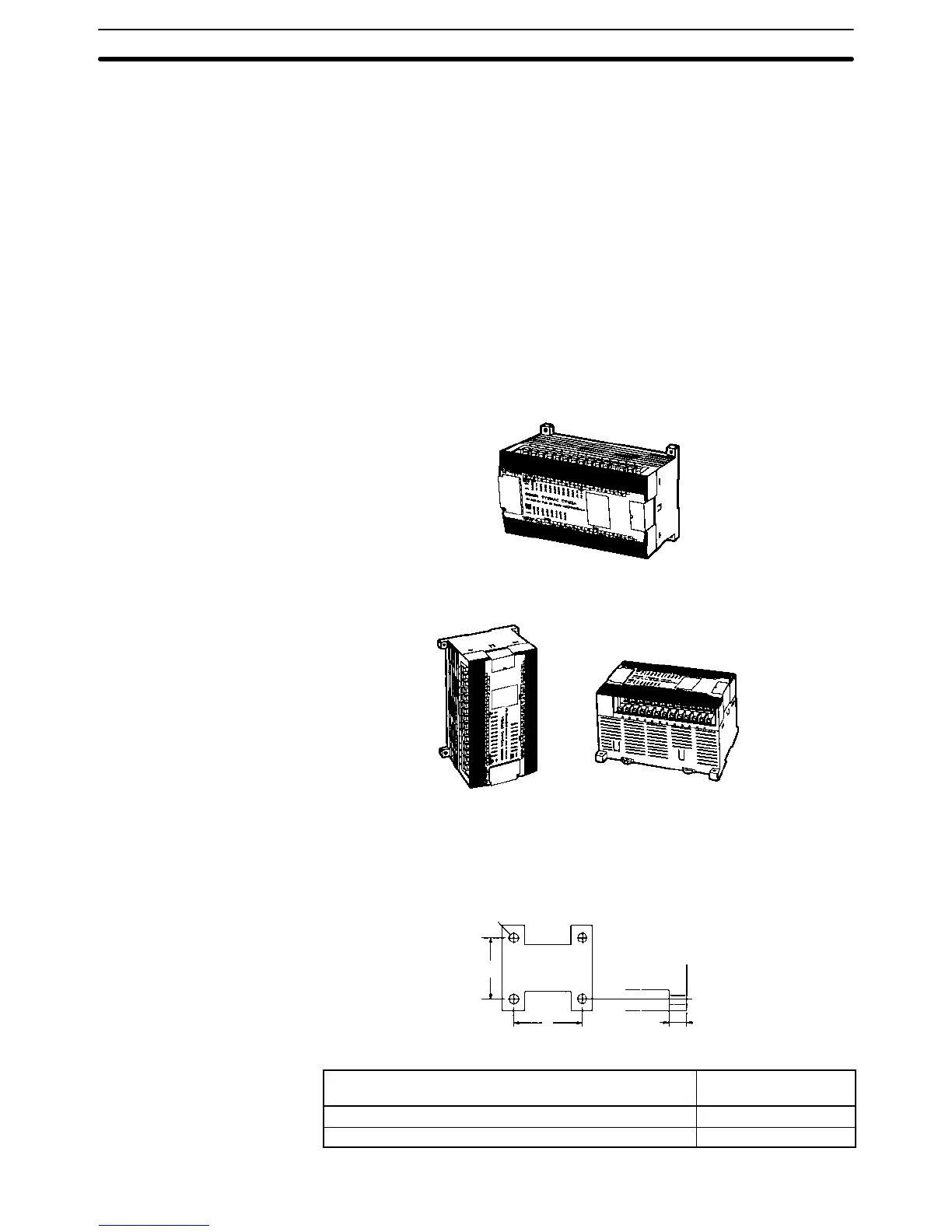
3-3-1 CPM2A Orientation
The CPM2A must be installed in the position shown below to ensure adequate
cooling.
Correct
Do not install the CPM2A in either of the following positions.
Incorrect Incorrect
3-3-2 CPM2A Installation
The CPM2A can be installed on a horizontal surface or on a DIN track.
Surface Installation Use the following pattern when installing a CPM2A CPU Unit, Expansion Unit, or
Expansion I/O Unit on a vertical surface. (Use M4 dia. x 15 screws.)
Unit
Four, M4 holes
8 mmA
100 mm
The width (A) between the mounting holes depends on the Unit.
Unit Width (A)
(tolerance: ±0.2 mm)
CPU Unit with 20/30 I/O terminals 120 mm
CPU Unit with 40 I/O terminals 140 mm
Installing the CPM2A
Section 3-3

 Loading...


