1-6SectionPreparation for Operation
26
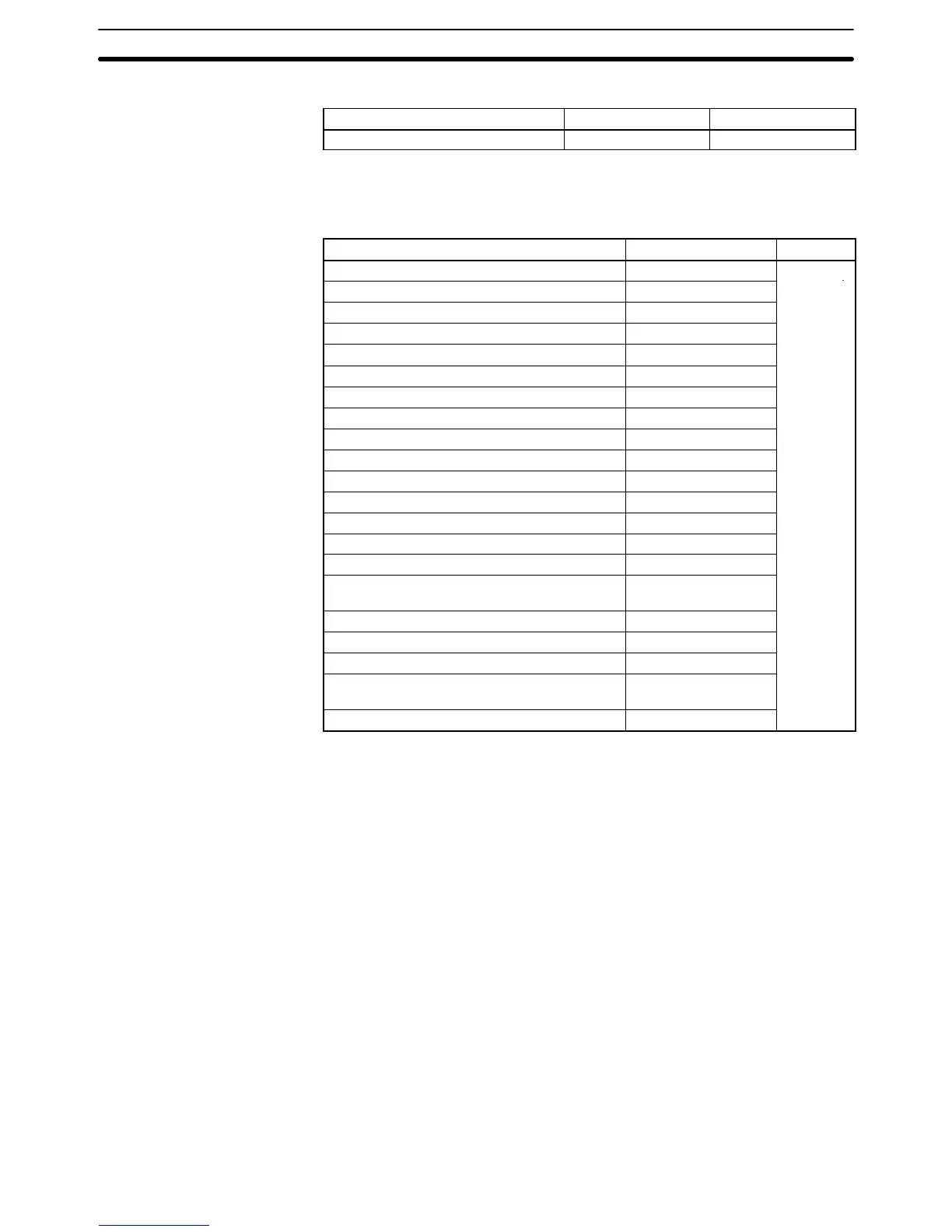
The following table shows differences in the DM area other than the PC Setup.
Function CPM2A CPM1A
Error Log Area DM 2000 to DM 2021 DM 1000 to DM 1021
Note CPM1A programs that use the Error Log Area cannot be used in the CPM2A
without editing the program to change the location of the Error Log Area.
The following table shows differences in the PC Setup.
Function CPM2A CPM1A
RS-232C Port Servicing Time Setting DM 6616 bits 00 to 07
Not
RS-232C Port Servicing Time Enable DM 6616 bits 08 to 15
supported
Pulse Output 0 Coordinate System DM 6629 bits 00 to 03
Pulse Output 1 Coordinate System DM 6629 bits 04 to 07
RS-232C Communications Settings Selector DM 6645 bits 00 to 03
RS-232C Port CTS Control Settings DM 6645 bits 04 to 07
RS-232C Port Link Words for 1:1 PC Link DM 6645 bits 08 to 11
RS-232C Port Communications Mode DM 6645 bits 12 to 15
RS-232C Port Baud Rate DM 6646 bits 00 to 07
RS-232C Port Frame Format DM 6646 bits 08 to 15
RS-232C Port Transmission Delay DM 6647
RS-232C Port Host Link Node Number DM 6648 bits 00 to 07
RS-232C Port No-protocol Start Code Enable DM 6648 bits 08 to 11
RS-232C Port No-protocol End Code Enable DM 6648 bits 12 to 15
RS-232C Port No-protocol Start Code Setting DM 6649 bits 00 to 07
RS-232C Port No-protocol End Code Setting
or Number of Bytes Received
DM 6649 bits 08 to 15
Peripheral Port No-protocol Start Code Enable DM 6653 bits 08 to 11
Peripheral Port No-protocol End Code Enable DM 6653 bits 12 to 15
Peripheral Port No-protocol Start Code Setting DM 6654 bits 00 to 07
Peripheral Port No-protocol End Code Setting
or Number of Bytes Received
DM 6654 bits 08 to 15
Battery Error Detect Setting DM 6655 bits 12 to 15
1-6 Preparation for Operation
Follow the steps listed below when setting up a CPM2A system.
1, 2, 3... 1. System Design
• Select a CPM2A CPU Unit, Expansion Units and Expansion I/O Units with
the specifications required in the controlled system.
• Design external fail-safe circuits such as interlock circuits and limit circuits.
Refer to 2-1 Specifications and 3-1 Design Precautions for details.
2. Installation
• Install the CPU Unit. (Surface-mount or DIN-track installation)
• Install the Expansion Unit(s) and Expansion I/O Unit(s).
Refer to 3-3 Installing the CPM2A and 3-4 Wiring and Connections for de-
tails.
3. Wiring
• Wire the power supply and I/O devices.
• Connect communications devices if necessary.
• Connect the Programming Console.
Refer to 3-4 Wiring and Connections for details.
DM Area Differences

 Loading...


