nputs.
IR 00006 12 to 15
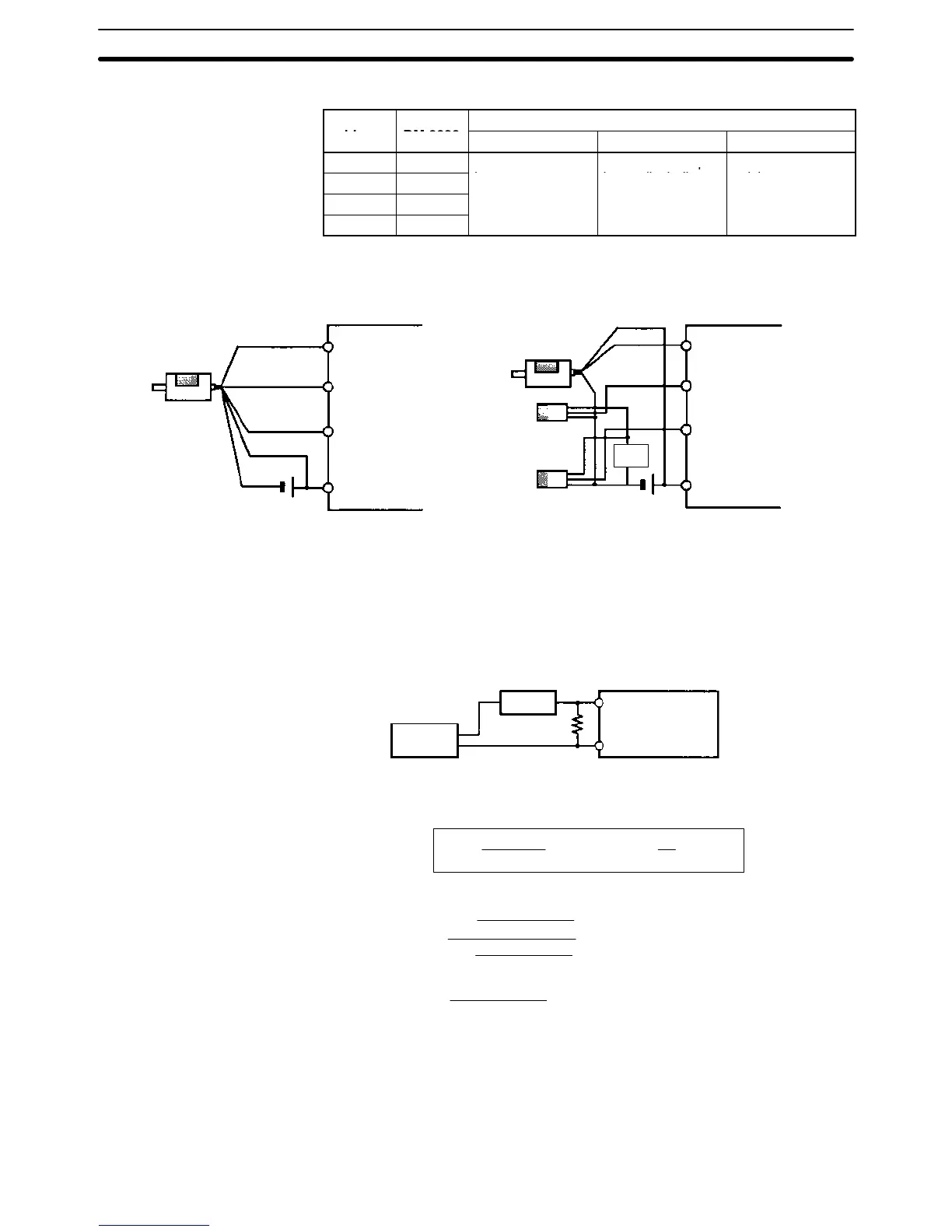
High-speed Counter Input Connection Examples
Differential Phase Mode
(Count frequency: 5 kHz)
E6B2-CWZ6C
Encoder
(NPN open-col-
lector output)
24 VDC
00000 A-phase input
00001 B-phase input
COM
00002 Z-phase input
Pulse Plus Direction Input mode
(Count frequency: 20 kHz)
E6A2-CS5C
Encoder
24 VDC
00000 Pulse input
00001 Direction input
COM
00002 Reset input
Sensor or
switch
CPM2A CPM2A
Sensor or
switch
Sensor
power
Black
White
Orange
Brown
Blue
Leakage Current A leakage current can cause false inputs when using 2-wire sensors (proximity
switches or photoelectric switches) or limit switches with LEDs. False inputs
won’t occur if the leakage current is less than 1.0 mA (2.5 mA for IN00000 to
IN00002). If the leakage current exceeds these values, insert a bleeder resistor
in the circuit to reduce the input impedance, as shown in the following diagram.
R
CPM2A
Input power
supply
Bleeder
resistor
2-wire sensor, etc.
I: Device’s leakage current (mA)
R: Bleeder resistance (kΩ)
W: Bleeder resistor’s power rating (W)
The equations above were derived from the following equations:
L
C
: CPM2A’s input impedance (kΩ)
I
C
: CPM2A’s input current (mA)
E
C
: CPM2A’s OFF voltage (V) = 5.0 V
R +
L
C
5.0
I L
C
–5.0
kW max. W +
2.3
R
Wmin.
I
R
Input voltage (24)
Input Current (I
C
)
R )
Input voltage (24)
Input Current (I
C
)
x OFF voltage (E
C
:5.0)
W y
Input voltage (24)
R
Input voltage (24) tolerance (4)
Refer to 2-1-3 I/O Specifications for details on the values L
C
, I
C
, and E
C
.
The input impedance, input current, and OFF voltage may vary depending on the
input being used. (IN00000 through IN00002 have different values.)
Sensor Surge Current If a sensor power supply is turned ON when the PC is ON and ready to receive
inputs, surge current from the sensor may result in an incorrect input. To prevent
improper operation, use the following type of programming in the ladder pro-
Wiring and Connections
Section 3-4

 Loading...


