EasyManua.ls Logo

Omron CPM2A - 11-2005 User Manual

Omron CPM2A - 11-2005
187 pages
To Next Page IconTo Next Page
To Previous Page IconTo Previous Page
Page #31 background imageLoading...
Page #31 background image
1-2SectionBasic System Configurations
10
A PC with 6 analog inputs and 3 analog outputs (the maximum) can be as-
sembled by connecting three Analog I/O Units. (Only one Analog I/O Unit can be
connected if an NT-AL001 Adapter is connected to the CPU Unit’s RS-232C
port.)
A PC with up to 6 temperature inputs for input from thermocouples or platinum
resistance thermometers can be assembled by connecting Temperature Sensor
Units.
CompoBus/S I/O Link Units (Slave Units) can be connected to a CPU Unit. I/O
data (8 inputs and 8 outputs) is transferred between the CPU Unit and the area
allocated to the CompoBus/S Slave. (The I/O data exchanged with the Slave is
internal data; there are no external input or output terminals.)
DeviceNet I/O Link Units can be connected to a CPU Unit. I/O data (32 inputs
and 32 outputs) is transferred between the CPU Unit and the area allocated to
the DeviceNet I/O Link Unit. (The I/O data exchanged with the Slave is internal
data; there are no external input or output terminals.)
Note 1. Different types of Expansion I/O Units or Expansion Units can be connected
at the same time. For example, an Expansion I/O Unit, an Analog I/O Unit, a
CompoBus/S I/O Link Unit, and DeviceNet I/O Link Unit can be connected to
the CPU Unit.
2. When an NT-AL001 Adapter is connected to the RS-232C port, only one Ex-
pansion Unit or Expansion I/O Unit can be connected to the CPU Unit be-
cause of power supply limitations.
Expansion I/O Units
8-point Input Unit 8-point Output Unit20-point I/O Unit
Unit Max. number
of Units
Inputs Outputs Model
Expansion
I/O Units
20 I/O
points
3 Units max.
(See note )
24 VDC Relays CPM1A-20EDR1
I
/O
Units points
12 inputs
(S
ee note.
)
24 VDC Sinking transistors CPM1A-20EDT
12
inputs
8 outputs
24 VDC Sourcing transistors CPM1A-20EDT1
8 inputs 24 VDC --- CPM1A-8ED
8 outputs
--- Relays CPM1A-8ER
p
--- Sinking Transistors CPM1A-8ET
--- Sourcing Transistors CPM1A-8ET1
Note Only one Expansion I/O Unit can be connected if an NT-AL001 Adapter is con-
nected to the CPU Unit’s RS-232C port.

Table of Contents

Question and Answer IconNeed help?

Do you have a question about the Omron CPM2A - 11-2005 and is the answer not in the manual?

Omron CPM2A - 11-2005 Specifications

General IconGeneral
CategoryController
ManufacturerOmron
Output TypeRelay
Input Voltage24 VDC
Supply Voltage100 to 240 VAC
Timer/Counter256
Communication PortRS-232
Operating Temperature0 to 55°C
Humidity10% to 90% RH (with no condensation)
Program Capacity2048 Steps

Summary

SECTION 1 Introduction

CPM2A Features and Functions

Describes the features and functions of the CPM2A PCs, covering basic and advanced capabilities.

SECTION 2 Unit Specifications and Components

Specifications

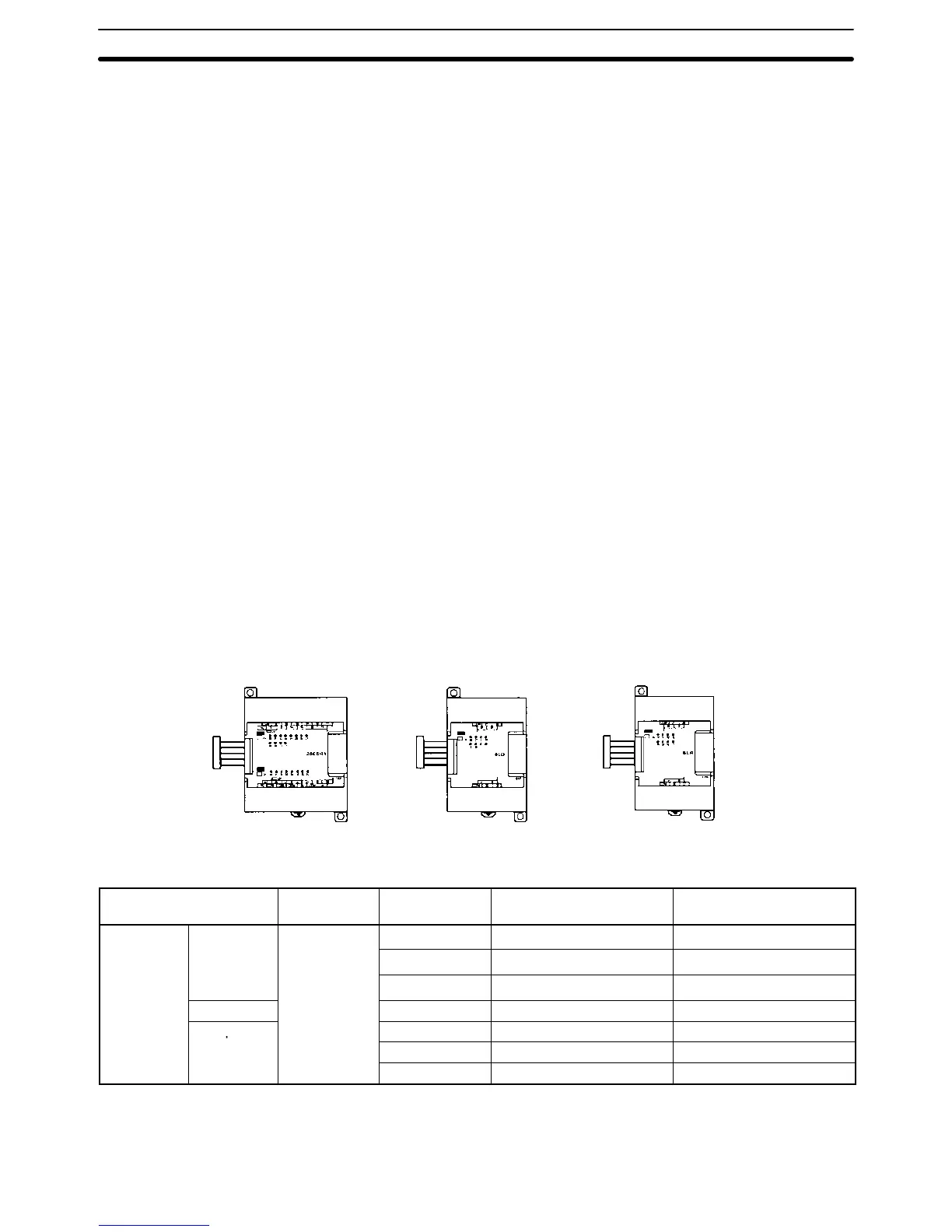
Presents detailed technical specifications for CPM2A CPU Units and expansion units.

SECTION 3 Installation and Wiring

Installing the CPM2A

Provides step-by-step instructions for physically installing the CPM2A CPU Unit and expansion units.

Wiring and Connections

Details the procedures for correctly wiring power supplies, I/O devices, and communication devices.

SECTION 4 Using a Programming Console

Programming Console Operations

Explains various operations and functions available when using a programming console with the CPM2A.

SECTION 5 Test Runs and Error Processing

Initial System Checks and Test Run Procedure

Outlines the procedures for initial system checks and performing test runs of the CPM2A.

Troubleshooting Flowcharts

Provides flowcharts to help diagnose and resolve operational errors and issues.

Related product manuals