!
45
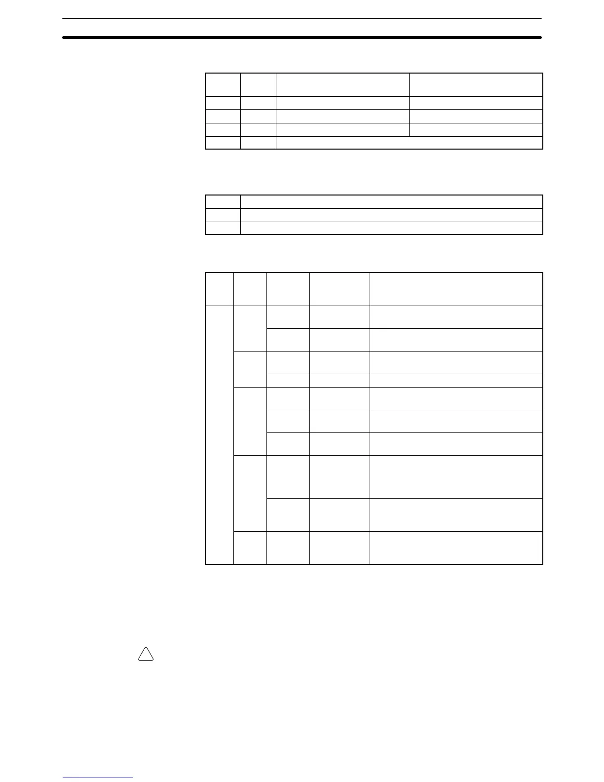
Baud Rate Setting
Pin 1 Pin 2 DeviceNet baud rate Max. transmission path
length (reference value)
OFF OFF 125 kbps 500 m max.
ON OFF 250 kbps 250 m max.
OFF ON 500 kbps 100 m max.
ON ON Do not set.
Output Hold Setting
Pin 4 Output treatment for communications errors
OFF Clear outputs when a communications error occurs.
ON Retain outputs when a communications error occurs.
4. LED Indicators
Indi-
ca-
tor
Color Status Definition Meaning
MS Green
ON Device
Operational
Normal operating status.
Flashing Device in
Standby
Reading switch settings.
Red
ON Unrecover-
able Fault
Unit hardware error: Watchdog timer error
Flashing Minor Fault Switch settings incorrect, etc.
--- OFF No Power Power isn’t being supplied, waiting for
initial processing, or Unit is being reset.
NS Green
ON On-line,
Connected.
Network is operating normally
(communications established)
Flashing On-line, Not
Connected
Network is operating normally, but
communications are not yet established.
Red
ON Fatal Com-
munications
Error
A fatal communications error has
occurred. Network communications are
not possible. Check for a node address
duplication or Bus Off error.
Flashing Non–fatal
communica-
tions error
Communications timeout or
communications error for some of the
slaves.
--- OFF Not
Powered/
Not On-Line
Checking for node address duplication on
the master, switch settings are incorrect,
or the power supply is OFF.
5. Expansion I/O Unit Connecting Cable
Connects the DeviceNet I/O Link Unit to the Expansion Connector on the
PC’s CPU Unit or another Expansion Unit. This cable cannot be removed.
Caution Do not touch the Expansion I/O Unit Connecting Cable while the power is being
supplied in order to prevent any malfunction due to static electricity.
6. Expansion Connector
Connects to another Expansion Unit or Expansion I/O Unit
Unit Components
Section 2-2

 Loading...


