6 - 9
6 Programless Communications
E5C-T Digital Temperature Controllers Programmable Type Communications Manual (H186)
6-2 E5@C-T Controller Setup
6
6-2-5 Areas and First Address of Linked Data
Communications Setting Level
Display condition: The Protocol Setting parameter must be set to fins or mcp4.
Note: 1 The First Address Upper Word and First Address Lower Word parameters together specify the first
address.
Example: If the first address is 123456, set the First Address Upper Word parameter to 12 and the First
Address Lower Word parameter to 3456.
2 Set the same first address in all of the E5@C-T Controllers (e.g., set the same value as the value that is
set for the E5@C-T with communications unit number 0).
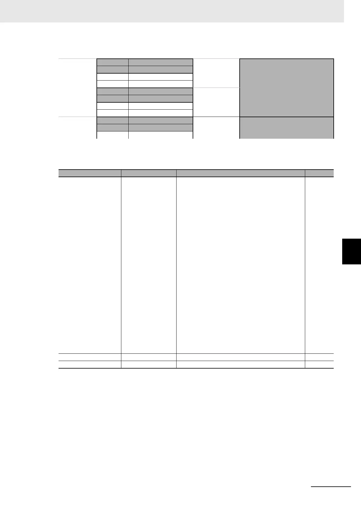
Address Data in PLC memory E5@C-T
Each E5@C-T
Controller is
allocated 70
words
XXXX Response Flag
←
Communications Unit Number 0
+1 Communications Status
+2 Monitor Value 1
· · ·
+25 Request Flag
→
+26 Operation Command Code
+27 Set Value 1
· · ·
+70 Response Flag
←
No.1+71 Communications Status
· · · · · ·
Parameter name Displayed characters Setting range Default
Area area 0: DM (D data registers)
1: EM0 (W link registers)
2: EM1 (R file registers)
3: EM2 (ZR file registers)
4: EM3
5: EM4
6: EM5
7: EM6
8: EM7
9: EM8
10: EM9
11: EMA
12: EMB
13: EMC
14: EMD
15: EME
16: EMF
17: EM10
18: EM11
19: EM12
20: EM13
21: EM14
22: EM15
23: EM16
24: EM17
25: EM18
Information in parentheses is applicable when the
Protocol Setting parameter is set to mcp4. Also, all set
values of 4 and higher specify D data registers.
0
First Address Upper Word adrh 0 to 99 0
First Address Lower Word adrl 0 to 9999 0

 Loading...


