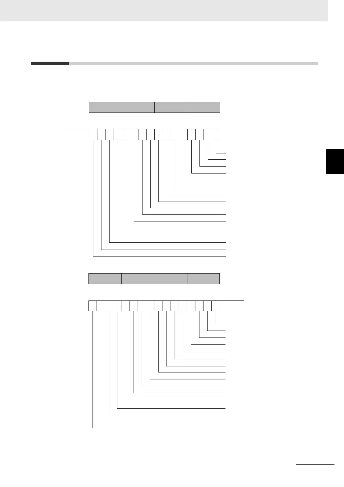
EasyManuals Logo
Home>Omron>Controller>E5*C Series

Omron E5*C Series Communications Manual

Omron E5*C Series
186 pages
To Next Page IconTo Next Page
To Previous Page IconTo Previous Page
Page #77 background imageLoading...
Page #77 background image
3 - 31
3 Communications Data for CompoWay/F
E5C-T Digital Temperature Controllers Programmable Type Communications Manual (H186)
3-2 Status and Status 2
3
3-2 Status and Status 2
The figure below shows the structure of the status data.
Status Structure
Bit position
Heater overcurrent (CT1)
Heater current hold (CT1)
A/D converter error
HS alarm (CT1)
Alarm 4
Input error
Potentiometer input error
Control output (heating)/open output
Control output (cooling)/close output
HB (heater burnout) alarm (CT1)
HB (heater burnout) alarm (CT2)
Alarm 1
Alarm 2
Alarm 3
Program end output
012345678910111213141516
Input errorOutputs Error status
Bit position
Event input 1
Event input 2
Event input 3
Event input 4
Write mode
Non-volatile memory
Setup area
AT execute/cancel
RUN/RESET
Communications writing
Auto/manual switch
Heater overcurrent (CT2)
Heater current hold (CT2)
HS alarm (CT2)
1516171819202122
0
232425262728293031
Operating statusError statusEvent inputs
0
0

Table of Contents

Other manuals for Omron E5*C Series

Questions and Answers:

Question and Answer IconNeed help?

Do you have a question about the Omron E5*C Series and is the answer not in the manual?

Omron E5*C Series Specifications

General IconGeneral
BrandOmron
ModelE5*C Series
CategoryController
LanguageEnglish

Related product manuals