6 Programless Communications
6 - 8
E5C-T Digital Temperature Controllers Programmable Type Communications Manual (H186)
Communications Setting Level
Display condition: The Protocol Setting parameter must be set to fins or mcp4
The Protocol Setting parameter must be set to cmp and the Communications Unit No. parameter must
be set to 0 (master).
Two areas are used in PLC memory by the E5@C-T, an upload area and a download area. The upload
area is used to monitor the process value, status, and other information from the E5@C-T. The down-
load area is used to write the fixed SP, segment SPs, segment times, alarm values, and other values to
the E5@C-T.
The Response Flag, Communications Status, Request Flag, and Operation Command Code all have
special functions that cannot be changed. Refer to the following sections for application methods.
Request Flag: 6-3-1 Controlling Programless Communications with the Request Flag
Response Flag: 6-3-2 Response Flag
Operation Command Code: 6-3-4 Operation Command Codes
Communications Status: 6-3-5 Confirming Operation of Programless Communications
The portion of PLC memory to use is set with the Area, First Address Upper Word, and First Address
Lower Word parameters.
Note: If more than one E5@C-T Controller is connected to the same communications line, set the starting address
to the same value for all of them. The E5
@C-T Controller with communications unit number 0 will use the
words that start from the specified starting address, the E5
@C-T Controller with unit number 1 will use the
words that start from the specified starting address plus 70 words, and the E5@C-T Controller with unit
number 2 will use the words that start from the specified starting address plus 140 words
Parameter name Displayed characters Setting range Default
Highest Communications Unit No. maxu 0 to 99 0
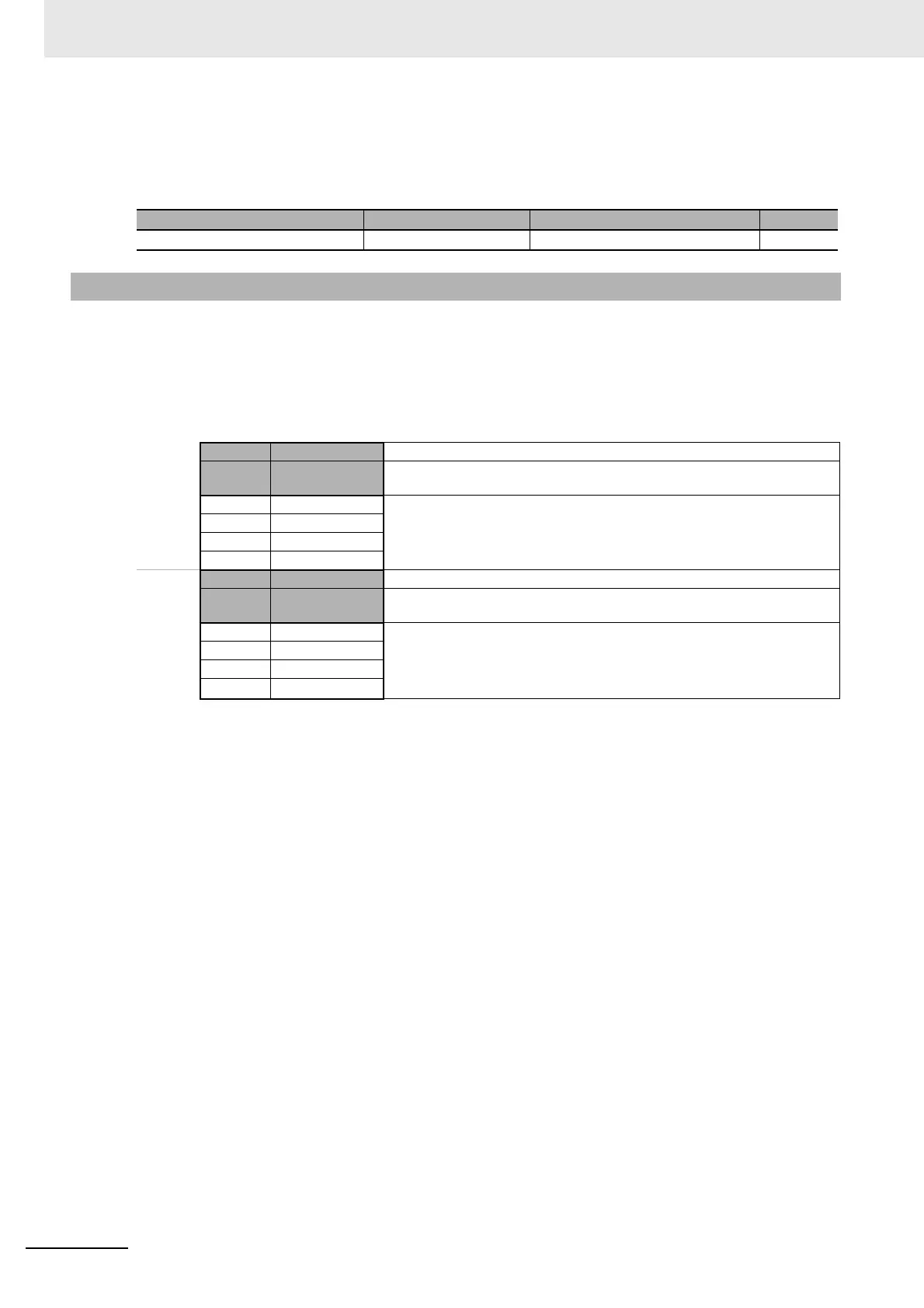
6-2-5 Areas and First Address of Linked Data
Address Data in PLC
memory
Upload
Area
XXXX Response Flag This flag indicates the completion of processing for the Request Flag.
+1 Communications
Status
The status that is given at this address is used in the PLC to check the operation
of programless communications.
+2 Monitor Value 1 Information from the E5@C-T, such as the PV or status, is set at these addresses.
The parameters that are actually used are set in the upload settings.
+3 Monitor Value 2
· · ·
+24 Monitor Value 23
Downloa
d Area
+25 Request Flag This flag is used to control programless communications.
+26 Operation
Command Code
The operation command that corresponds to the code is sent.
+27 Set Value 1 The set values at these addresses are written to the E5@C-T, such as to the fixed
SP, segment SPs, segment times, and alarm values. The parameters that are
actually used are set in the download settings.
+28 Set Value 2
· · ·
+69 Set Value 43

 Loading...


