Com Data
for Modbus
SECTION 6 Communications Data for Modbus
6-2
6.1 Variable Area (Setting Range) List
• Four-byte Mode
One element uses 2 bytes of data (H'0000 to H'FFFF), so specify two-
element units. Reading and writing in 4-byte units is executed by speci-
fying an even address and specifying the number of elements in
multiples of 2.
• Two-byte Mode
One element uses 2 bytes of data (H'0000 to H'FFFF), so specify one-
element units. Reading and writing in 2-byte data units is executed by
specifying 1-element units.
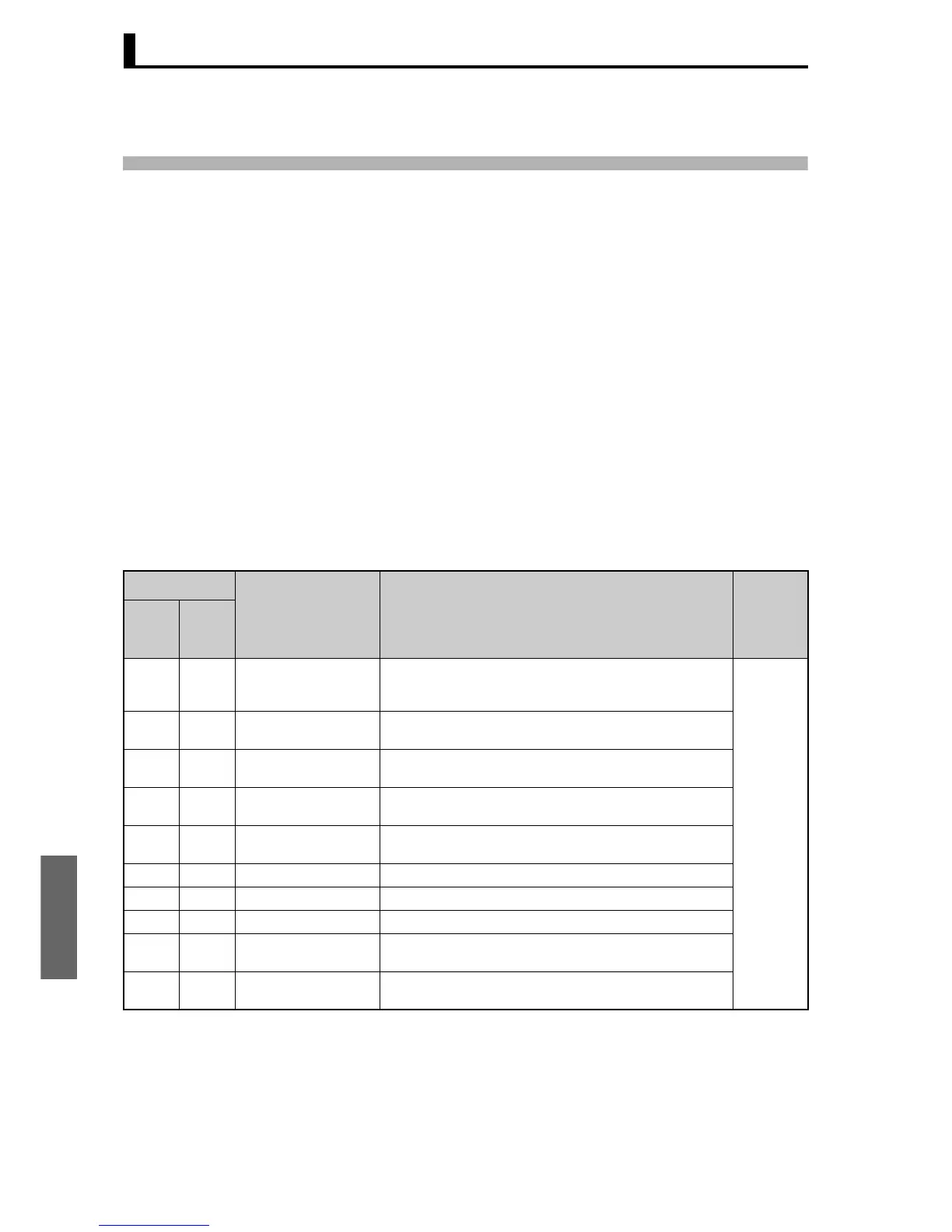
The following table lists the variable area. Items expressed in
hexadecimal in the “Set (monitor) value” column are the setting range in
the Modbus specifications. Values in parentheses “()” are the actual
setting range.
When there is a section reference for a setting item, refer to that
reference for details.
Note 1: Not displayed on the Controller display.
Note 2: In 2-byte mode, the rightmost 16 bits are read.
Address
Parameter name Setting (monitor) value LevelFour-
byte
mode
Two-
byte
mode
0000 2000 PV Temperature: Use the specified range for each sensor.
Analog: Scaling lower limit − 5% FS to Scaling upper limit + 5%
FS
Operation
0002 2001 Status (See notes 1 and
2.)
See the 6.2 Status and status 2 for details.
0004 2002 Internal Set Point (See
note 1.)
SP lower limit to SP upper limit
0006 2003 Heater Current 1 Value
Monitor
H'00000000 to H'00000226 (0.0 to 55.0)
0008 2004 MV Monitor (Heating) Standard: H'FFFFFFCE to H'0000041A (−5.0 to 105.0)
Heating and cooling: H'00000000 to H'0000041A (0.0 to 105.0)
000A 2005 MV Monitor (Cooling) H'00000000 to H'0000041A (0.0 to 105.0)
0106 2103 Set Point SP lower limit to SP upper limit
0108 2104 Alarm Value 1 H'FFFFF831 to H'0000270F (−1999 to 9999)
010A 2105 Alarm Value Upper Limit
1
H'FFFFF831 to H'0000270F (−1999 to 9999)
010C 2106 Alarm Value Lower Limit
1
H'FFFFF831 to H'0000270F (−1999 to 9999)

 Loading...


