CompoWay/F
2.2 Structure of Command Text
2-7
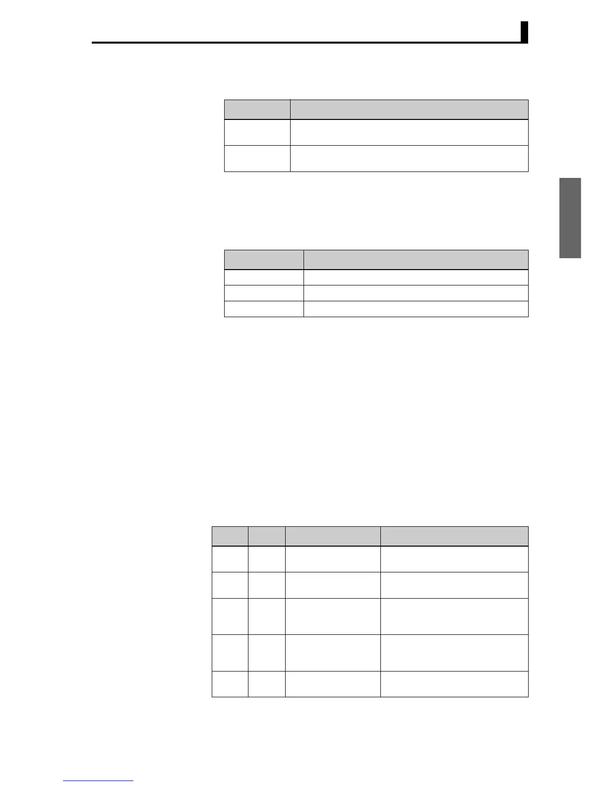
The following table summarizes setup areas 0 and 1.
The type code depends on the parameter. Refer to 3.1 Variable Area
(Setting Range) List for details.
The variable type is converted to 2-byte ASCII and loaded to the frame.
The following table shows the available variable types.
Note: Setup area 1 has no read-only parameters, so there is no variable
type “C2.”
■ Addresses An address is appended to each of the variable types. Express
addresses in 2-byte hexadecimal and append them for the specified
access size. The address depends on the parameter. Refer to 3.1
Variable Area (Setting Range) List for details.
■ Number of Elements
The number of elements is expressed in 2-byte hexadecimal. The range
that can be specified for the number of elements depends on the
command. Refer to 2.3 Detailed Description of the Services for details.
■ List of Services (Main Request Codes and Sub-Request Codes)
Area Description
Setup area 0 This area groups together the protect, manual control, opera-
tion, and adjustment levels.
Setup area 1 This area groups together the initial setting, communications
setting, advanced function setting, and calibration levels.
Variable type Description
C0/80 R/O (read only) parameter for setup area 0.
C1/81 R/W parameter for setup area 0.
C3/83 R/W parameter for setup area 1.
MRC SRC Name of service Processing
01 01 Read Variable Area This service reads from the variable
area.
01 02 Write Variable Area This service writes to the variable
area.
01 04 Composite Read from
Variable Area
This service reads from the variable
area in the order specified by the
parameters.
01 13 Composite Write to
Variable Area
This service writes to the variable
area in the order specified by the
parameters.
05 03 Read Controller
Attributes
This service reads the model num-
ber and communications buffer size.

 Loading...


