A Appendices
A - 34
E5@C Digital Temperature Controllers User’s Manual (H174)
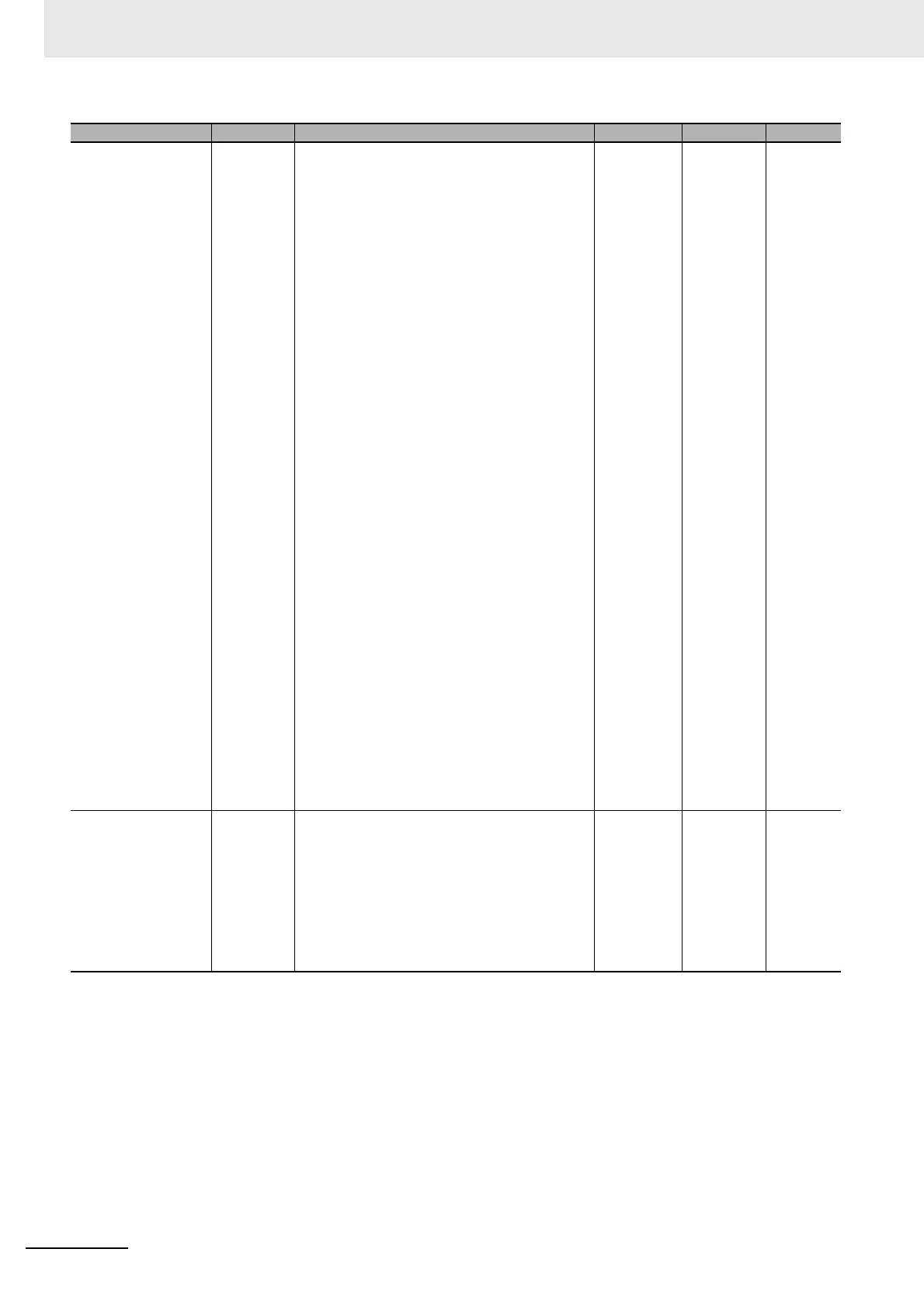
Control Output 1
Assignment
out1
Relay Output or Voltage Output (for Driving SSR)
*2
ONone
NONE: No assignment none
O: Control output (heating) o
C-O: Control output (cooling) c-o
ALM1: Alarm 1 alm1
ALM2: Alarm 2 alm2
ALM3: Alarm 3 alm3
ALM4: Alarm 4 alm4
HA: Heater alarm (HB + HS) ha
HB: Heater burnout alarm (HB) hb
HS: Heater short alarm (HS) hs
S.ERR: Input error s.err
RS.ER: Remote SP input error rs.er
P.END: Program End output
*3
p.end
RUN: RUN output run
ALM: Integrated alarm alm
WR1: Work bit 1
*4
wr1
WR2: Work bit 2
*4
wr2
WR3: Work bit 3
*4
wr3
WR4: Work bit 4
*4
wr4
WR5: Work bit 5
*4
wr5
WR6: Work bit 6
*4
wr6
WR7: Work bit 7
*4
wr7
WR8: Work bit 8
*4
wr8
For Linear Current Output
*2
TCMV: Simple transfer MV (cooling)
*5
tcmv
T-MV: Simple transfer MV (heating)
*5
t-mv
T-PV: Simple transfer PV
*5
t-pv
TSPM: Simple transfer ramp SP
*5
tspm
T-SP: Simple transfer SP
*5
t-sp
NONE: Not assigned. none
O: Control output (heating) o
C-O: Control output (cooling) c-o
Control Output 2
Assignment
out2 Same as for the Control Output 1 Assignment
parameter except for the setting (monitor) value
marked with
*5
.
Same as for
the Control
Output 1
Assignment
parameter
except for the
setting
(monitor)
value marked
with
*5
.
NONE None
Parameters Characters Setting (monitor) value Display Default Unit

 Loading...