8-3
Remote I/O Communications Performance Section 6-1
Communications
Performance
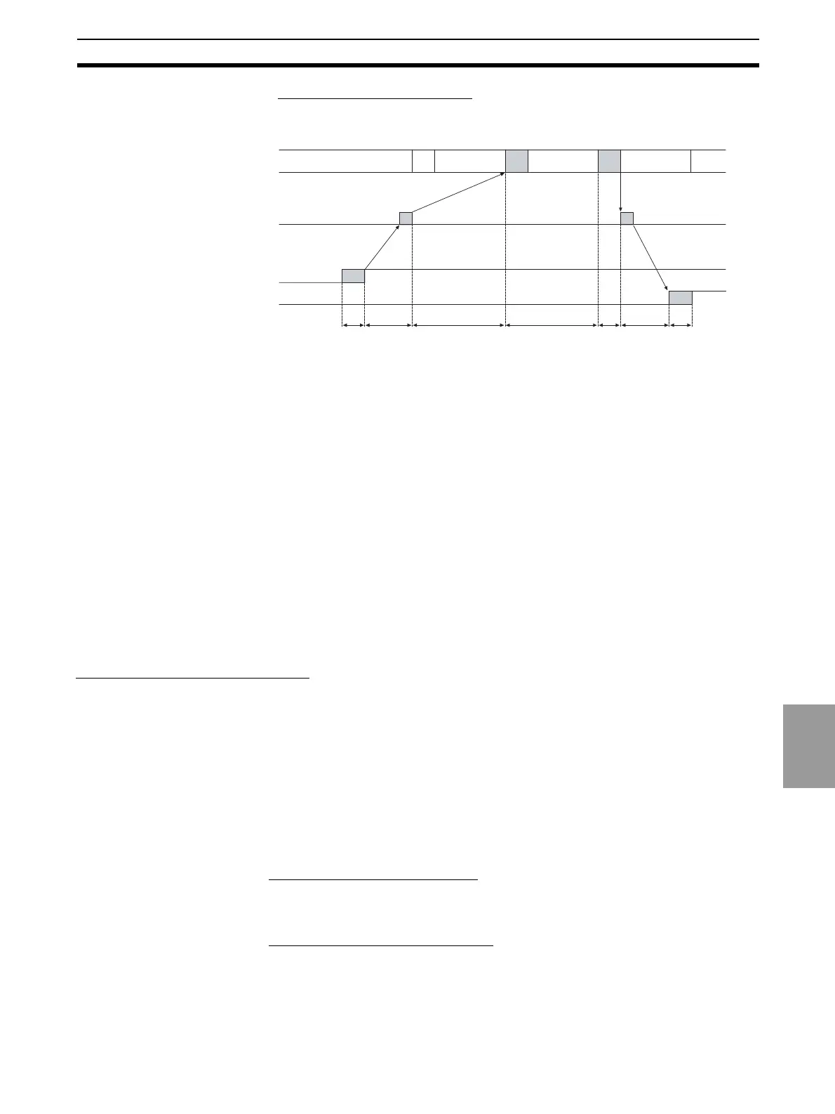
Maximum I/O Response Time
The maximum I/O response time occurs under the conditions shown in the
following diagram.
T
IN
: ON/OFF delay time of the input slave (0 used as minimum value)
T
OUT
: ON/OFF delay time of the output slave (0 used as minimum value)
T
RM
: Communications time for entire network
T
PC
: Cycle time of PLC
T
RF
: DeviceNet Unit refresh time at PLC
Note Refer to the operation manuals for the slaves for the input slave ON/OFF
delay times and the output slave ON/OFF delay times. Refer to 6-1-2 Com-
munications Cycle time and Refresh Processing Time and to the operation
manual for the PLC for the PLC cycle time.
The maximum I/O refresh time can be calculated as follows:
T
MAX
= T
IN
+ 2 x T
RM
+ 2 x T
PC
+ T
RF
+ T
OUT
6-1-2 Communications Cycle time and Refresh Processing Time
This section describes the communications cycle time and refresh processing
time, which are required to calculate various processing times for DeviceNet.
Communications Cycle Time
The communications cycle time is the time from the completion of a slave's
I/O communications processing until I/O communications with the same slave
are processed again. The communications cycle time is the maximum com-
munications cycle time T
IN
+ T
OUT
.
The equations used to calculate the communications cycle time are described
here.
Communications Cycle Time Equations
Total communications cycle time = IN communications cycle time + OUT com-
munications cycle time.
■ IN Communications Cycle Time
IN communications cycle time = (39 ms + 8 ms x number of allocated data) +
(6 ms × total allocated words in IN Areas 1 and 2)
■ OUT Communications Cycle Time
OUT communications cycle time = (29 ms + 27 ms x number of allocated
data) + (7 ms
× total allocated words in OUT Areas 1 and 2)
PLC
Master Unit
Input
T
IN
Output
T
RM
T
PC
T
PC
T
RM
T
RF
T
OUT
Program
execution
Program
execution
Program
execution

 Loading...