3-6
NX Units
The NX Units perform I/O processing with connected external devices. The NX Units refers to NX-ser-
ies NX-££££££ Units.
Up to eight NX Units can be connected to the CPU Unit.
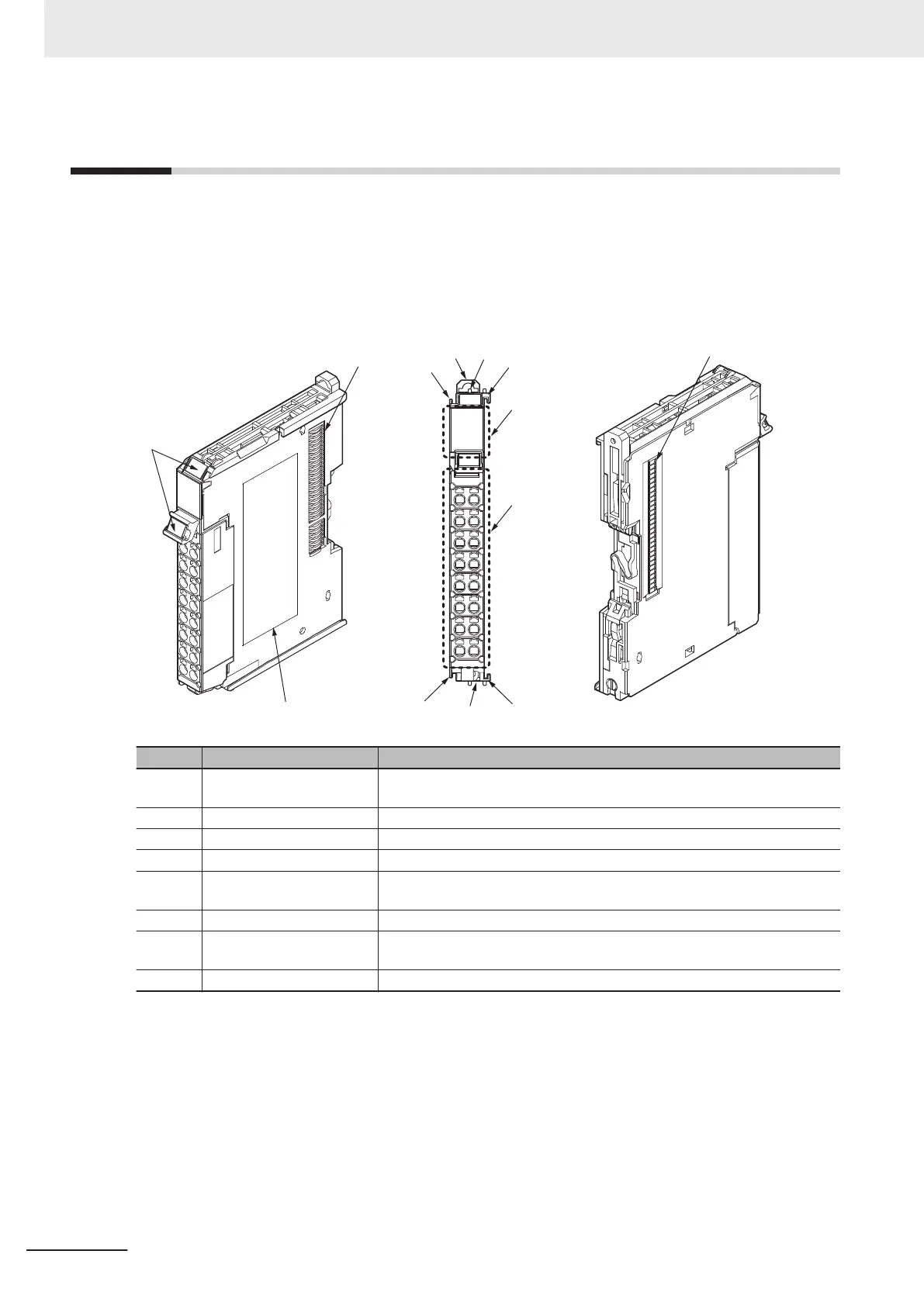
The following is an example of NX Unit’s part names and functions.
For details on the part names and functions of NX Units, refer to the user’s manual for each NX Unit.
(A)
(H)
(B)
(B)
(C)
(G)
(F)
(C)
(C)
(C)
(D)
(E)
(E)
Symbol Name Function
A Marker attachment location The locations where markers are attached. OMRON markers are pre-installed at
the factory. Y
ou can also install commercially available markers.
B NX bus connector This connector is used to connect another Unit.
C Unit hookup guides These guides are used to connect two Units.
D DIN Track mounting hook This hook is used to mount the NX Unit to a DIN Track.
E Protrusions for removing the
Unit
The protrusions to hold when removing the Unit.
F Indicators The indicators show the current operating status of the Unit.
G Terminal block The terminal block is used to connect external devices.
The number of terminals depends on the type of Unit.
H Unit specifications The specifications of the Unit are given here.
3 Configuration Units
3-32
NX-series NX1P2 CPU Unit Hardware User’s Manual (W578)

 Loading...


