2-1-2
NX Unit Configuration
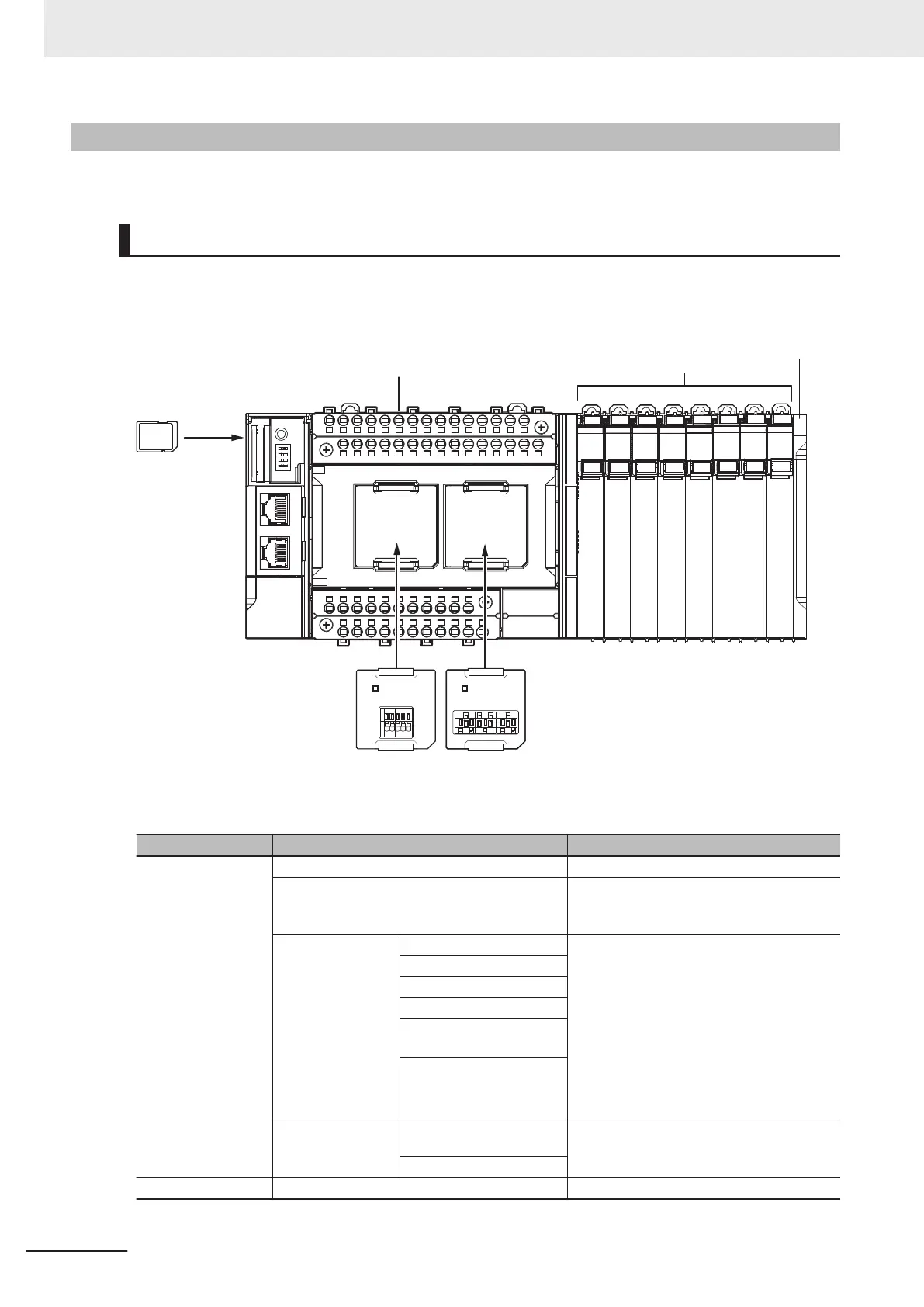
The following shows the configuration of NX Units.
CPU Rack
The CPU Rack consists of an NX-series NX1P2 CPU Unit, NX Units, and an End Cover.
Up to eight NX Units can be connected.
NX-series NX1P2 CPU Unit
Option Board
(1 or 2)
SD Memory
Card
End CoverNX Units
(8 Units max.)
Series Configuration Remarks
NX-series NX-series NX1P2 CPU Unit One required for every CPU Rack.
End Cover Must be connected to the right end of the CPU
Rack. One End Cover is provided with the
CPU Unit.
NX Unit Digital I/O Unit Up to eight Units can be mounted on each
CPU Rack.
Refer to A-4 Support Functions of the CPU
Units and Restrictions on the NX Units on page
A-9 for information such as restrictions on
the NX Units.
For information on the most recent lineup of
NX Units, refer to NX-series catalogs or OM-
RON websites, or ask your OMRON represen-
tative.
Analog I/O Unit
System Unit
Position Interface Unit
Communications Interface
Unit
Load Cell Input Unit
Option Board Serial Communications Op-
tion Board
One or two Option Boards can be connected to
the CPU Unit.
Analog I/O Option Board
NJ/NX-series SD Memory Card Install as required.
2 System Configuration
2-4
NX-series NX1P2 CPU Unit Hardware User’s Manual (W578)

 Loading...


