3-12
3-1 Servo Drive Specifications
3
Specifications
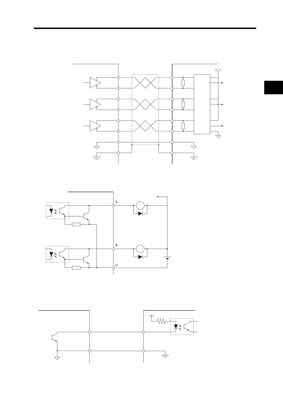
Control Output Circuits
Position Feedback Output
Control/Alarm Outputs
Phase-Z Output (Open-collector Output)
ControllerServo Drive
+A15
−A16
+B18
−B17
+Z19
−Z20
GND14
FGShell
+A
−A
+B
−B
+Z
−Z
GND
Phase A
Phase B
Phase Z
Phase A
Phase B
Phase Z
Output line driver
AM26C31 or
equivalent
FG
0 V
R = 120 to 220 Ω
R
R
R
FG
0 V
0 V
+5 V
Applicable line receiver
AM26C32 or equivalent
Servo Drive
External power supply
24 VDC ±1 V
X
Di
To other output
circuits
Maximum operating voltage: 30 VDC
Maximum output current: 50 mA
Di: Diode for preventing surge voltage
(Use high-speed diodes.)
X
Di
Servo Drive
Maximum operating voltage: 30 VD
Maximum output current: 50 mA
Controller
FG
GND
Z21
14
 Loading...


