6-18
Set Values
•Set
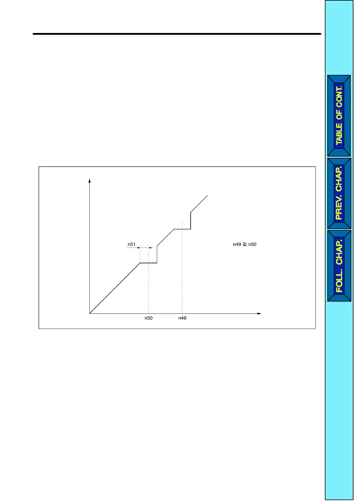
n49 and n50 for jump frequencies 1 and 2 to the central values of jumping frequen
-
cies.
•These values must satisfy the following condition.
n49
n50
•The value in n51 must be set for the jump width.
•This function is disabled with n51 set to 0.0.
•The
operation of the Inverter within the dead bands is prohibited. While the Inverter is
in
acceleration or deceleration control, however
, the Inverter does not jump the bands
but changes the frequency smoothly.
Frequency Jump Function
Output
frequency
Reference
frequency
6-7-6 Frequency Detection Function
•The 3G3JV has the following frequency detection functions.
Frequency Detection:
Detects that the frequency reference coincides with the output frequency.
Frequency Detection Levels 1 and 2:
Detects
that the output frequency is
the same as or higher or lower than the set value
(frequency detection level) in n58.
Advanced Operation Chapter
6
 Loading...


