2-29
Reactor Effects
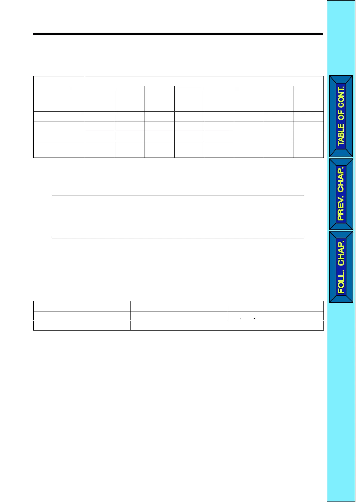
Harmonics
are ef
fectively suppressed when the DC reactor is used with the AC reactor
as shown in the following table.
Harmonics
Harmonic generation rate (%)
suppression
method
5th
har-
monic
7th
har-
monic
11th
har-
monic
13th
har-
monic
17th
har-
monic
19th
har-
monic
23rd
har-
monic
25th
har-
monic
No reactor 65 41 8.5 7.7 4.3 3.1 2.6 1.8
AC reactor 38 14.5 7.4 3.4 3.2 1.9 1.7 1.3
DC reactor 30 13 8.4 5 4.7 3.2 3.0 2.2
DC and AC
reactors
28 9.1 7.2 4.1 3.2 2.4 1.6 1.4
2-2-5 Wiring Control Circuit Terminals
A control signal line must be 50 m maximum and separated from power
lines.
The
frequency reference must be input into the
Inverter through shielded,
twisted-pair wires.
H Wiring Sequence I/O Terminals
Wire
the sequence input terminals (S1 to S5 and SC) and multi-function contact output
terminals (MA, MB, and MC) as described below.
D Wires Used
Wire type Wire size Wire to be used
Single wire 0.5 to 1.25 mm
2
Polyethylene-shielded cable
Stranded wire 0.5 to 0.75 mm
2
o yet y e e s e ded cab e
Design Chapter
2
 Loading...


